YOKOGAWA DrvPIII UR5AP3 Скачать руководство пользователя страница 72


5-14 


TI 71M01D06-01EN  3rd Edition: 2012.12.01 

19

36

1

3

2

1

18

36

21

20

19


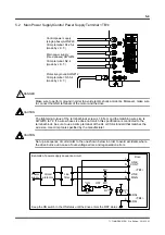
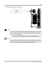
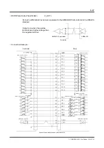
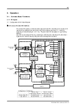
5.9  Controller Interface Connector <CN4> 

 
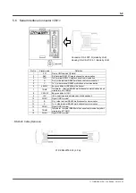
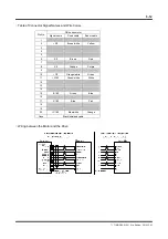
5.9.1  Contact I/O Interface 


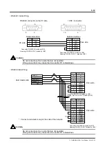
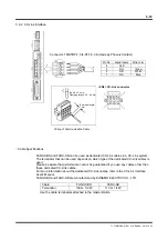
 Cable Specifications 


Interface 

AWG#28 to AWG#20 (0.08 ~ 0.5mm

2

), cable with a common 

shield, external diameter 

14mm or less, length 3m or less 

Option cable: C1P-ENN-4202-




Connector: PCR-S36FS (made by Honda Tsushin Kogyo)
Hosing: PCR-LS36LA (made by Honda Tsushin Kogyo)


<CN4> connector

Case ground (shielded cable)

Insertion surface

Soldered surface

Cable: UL2464 AWG28X25P


Содержание DrvPIII UR5AP3

Страница 1: ...71M01D06 01EN Yokogawa Electric Corporation 3rd Edition 2012 12 01 Technical Information Direct Drive Motor DYNASERV DR5A Type Intelligent Drive DrvPIII UR5AP3 Type Technical Information TI 71M01D06 0...

Страница 2: ......

Страница 3: ...Corporation No part of this document may be reproduced or transferred sold or distributed to the third party Strategic Goods Advisory It is required to obtain approval from the Japanese government to...

Страница 4: ...may be lost In such an event we make no warranties for the quality performance functions and safety of the product If you install protection safety circuits for the product or systems that use this pr...

Страница 5: ...Keep the original storage media of this software in a safe place If you do not have the original media we may decline to offer our prescribed quality warranty and maintenance services Reverse enginee...

Страница 6: ...of 1 mm or more on both sides If force is applied to the hollow hole in the DM motor the internal encoder may be damaged The DR motor has a hollow hole in its casting so take the dimensional allowance...

Страница 7: ...s the motor s five digit model and suffix code DM or DR must match the drive s model and suffix code UD G3 or UR G3 respectively In addition the current of the drive must also match the motor requirem...

Страница 8: ...lter 2 Then please tune the servo Prepare a fixture in the control panel or on the machine fix the cables to the fixture near the connectors so that external force is not applied to the connectors A p...

Страница 9: ...5 3 Connector 2 14 2 5 4 Terminals 2 14 2 6 Precautions at Installation Moving and Storage 2 15 2 6 1 Installation of the Motor 2 15 2 6 2 Installation of the Drive 2 17 2 7 Stop Function in Error St...

Страница 10: ...erial Interface Connector CN1 5 9 5 7 Encoder Resolver Connector CN2 5 11 5 8 Analog Monitor Connector CN3 5 13 5 9 Controller Interface Connector CN4 5 14 5 9 1 Contact I O Interface 5 14 5 9 2 CC Li...

Страница 11: ...Parameter Change 6 98 6 4 10 Conditional Branch 6 102 6 4 11 Command 6 104 6 4 12 Startup Operation 6 107 6 5 Control Using the PLC 6 108 6 6 Position Settling Signal 6 109 6 7 Signal Monitor Functio...

Страница 12: ...nitor 8 29 8 5 6 FFT Velocity Loop Transfer Characteristic Analysis Function 8 30 8 6 Details of the Data Management Group Function 8 31 8 6 1 parameters 8 31 8 6 2 Table Data Function 8 36 8 6 3 I O...

Страница 13: ...the hollow hole 150mm output torque 300 to 500 Nm 1 2 DrvPIII Drive UR5AP3 Type The intelligent drive DrvPIII 4 kW model UR5AP3 type is a direct drive servo motor drive designed exclusively for positi...

Страница 14: ...diately Name of product accessory Shape Remarks Motor unit The shape varies depending on the model and suffix code you ordered Drive unit Drive The shape varies depending on the model and suffix code...

Страница 15: ...n Japan DR5A 500G Label Motor model suffix code Serial number 203MM12345A1 Faceplate of the Drive 203MM12345A1 35 3ARMS DUTY30 0 230V 0 210Hz 3PHASE NO 21 6ARMS 200 230V 50 60Hz 3PHASE 500N 1SE 2SA N...

Страница 16: ......

Страница 17: ...ion positioning Encoder resolution p rev 851 968 Repeatability accuracy arc sec 3 Absolute accuracy arc sec 45 Number of origin pulses p rev 104 Maximum power consumption 200 V kVA 7 6 7 3 7 0 Rated p...

Страница 18: ...ion Temperature 0 45 C Standard 0 40 C CE continuous rating Humidity 20 85 RH No condensation Storage Temperature 20 85 C Humidity 20 85 RH No condensation Atmosphere Must be no corrosive gasses dust...

Страница 19: ...peed 38 400 bps Multi channel RS485 Max 10 channels Controller Interface Contact I O XA for interface type and specification No of input points 12 points No of output points 6 points with a terminal a...

Страница 20: ...2 4 TI71M01D06 01EN 3rd Edition 2012 12 01 2 2 Torque Velocity Characteristics DR5A Type Motor 0 0 5 1 0 1 5 2 0 0 100 200 300 400 500 DR5A 500 DR5A 400 DR5A 300 Velocity rps Maximum output torque N m...

Страница 21: ...rd test TC180 Test result attached absolute accuracy 180 seconds Positioning accuracy A4 Standard accuracy core run out surface run out 100um or less Termination option Motor cable 02 Open leads core...

Страница 22: ...urrent Power supply voltage Interface specification Supported standard UR5AP3 300 N 1S E 2 XA C1 N CN CN4 400 500 The motors and drives are compatible only among the same models In other words in the...

Страница 23: ...r Cable Model and Suffix Code Selection List Model Suffix code Description Drive type Drive current Cable type Termination option Drive side Termination option Motor side Cable length C1E S E 1 2 01 0...

Страница 24: ...Selection List Model Suffix code Description Drive type Drive current Cable type Termination option Drive side Termination option Motor side Cable length C1M N E 1 2 01 02 03 01 02 06 005 010 015 020...

Страница 25: ...inimum 002 20 cm maximum 050 5 m See the model name specification code selection table 22 With DA 15PF N and DA C8 J01 F4 1 made by JAE 42 With PCR S36FS and PCR LS36LA made by Honda Tsushin Kogyo Dri...

Страница 26: ...tor MS3106B20 4S Clamp MS3057 12A Canon connector made by JAE Connector MS3101B20 4P Clamp MS3057 12A 08 Encoder resolver cable Connector PCR S20FS Cover PCR LS20LA1 Made by Honda Tsushin Kogyo C1E EC...

Страница 27: ...AWG 12 3 5mm2 Insulating material external diameter 3 5mm Finished external diameter 11 0mm UL style 2464 2 50A Specification Robot Cable Identification of core wire Layout number 1 2 3 4 Color of ins...

Страница 28: ...1 Core No 2 Core No 1 Core No 2 1 Orange Red 1 Blue or black 1 16 Orange Red 4 Blue or black 4 2 Gray Red 1 Blue or black 1 17 Gray Red 4 Blue or black 4 3 White Red 1 Blue or black 1 18 White Red 4 B...

Страница 29: ...W direction 3 Axial fluctuation Specified by the suffix code Cable terminal treatment varies depending on the suffix code Cable length Encoder cable L 1 See the standard specifications 3 Radial fluctu...

Страница 30: ...by Honda Tsushin Kogyo Encoder Resolver Connector Connector PCR S20FS made by Honda Tsushin Kogyo Housing PCR LS20LA1 made by Honda Tsushin Kogyo Controller Connector CC Link Connector TMSTBP 2 5 4 S...

Страница 31: ...load securely using screws on the load mounting surface the upper surface of the motor Allow for a clearance of 1mm or more between the upper edge of the motor and the load and other structures so tha...

Страница 32: ...otor may be impaired Prevent areas other than the load mounting surface and the stator such as cables and internal parts of the motor from being subjected to the solvent and the left over coating Be c...

Страница 33: ...ive in an atmosphere with high temperature high humidity or which contains dust dirt metal powder corrosive gasses etc Drive environment specification Remarks At operation Ambient temperature 0 50 C A...

Страница 34: ...downward up side down or sideways see the figures below Allow a clearance of 50mm or more above and below the drive and 25mm or more on the left and right sides for ventilation Moreover do not block...

Страница 35: ...nel Also the holding time length differs depending on the drive power output Detecting condition for the power failure is variable by the power monitoring cycle setup by the parameter 110 System setup...

Страница 36: ...under power failure or instant power failure In this case the motor may run freely Be sure to take steps to secure safety such as using an external brake system If you select Servo OFF immediately the...

Страница 37: ...ta parameters table data and I O data is stored in the EEPROM built into the drive There is a restriction on the number of times to overwrite the data due to the EEPROM characteristics The number of a...

Страница 38: ...fety Precautions 1 Use 75 degrees Celsius CU wire only 2 Open Type Equipment 3 Maximum surrounding air temperature 50 degrees Celsius 4 Install device in pollution degree environment 5 Suitable for us...

Страница 39: ...is required Please contact Yokogawa about external resistors Limits on Regeneration Resistor Power Consumption to Current Squared Duty 0 20 40 60 80 100 120 140 0 10 20 30 40 50 DR5A 300 DR5A 400 DR5A...

Страница 40: ...the load inertia and rotor inertia is converted into current by the motor and consumed by motor loss coil copper loss and power AMP loss Excessive kinetic energy is used to charge a smoothing capacit...

Страница 41: ...peak value it must be converted to the actual value The peak current value is obtained from the following formula A 8 0 P TI M K T I The actual current value is obtained from the following formula Ar...

Страница 42: ...regenerative resistor The power consumed by the regenerative resistor during operation is obtained from the following formula CY RG RG t E P Parameters for each motor and drive The following table sho...

Страница 43: ...WM conversion Detection XA cintact I O Internal feed forward Rush prevention Insulated output Logic I O initial value Scaling conversion n m Insulate dinput Control power supply Hard I O logical setti...

Страница 44: ...12 12 01 3 2 Contact I O Interface 3 2 1 Contact I O The contact I O is a contact I O type interface for easily connecting with a general purpose PLC It provides 12 input points and 6 output points Fo...

Страница 45: ...nction CC Link version CC Link Ver 1 10 Ver 2 00 and CC Link LT are available for the CC Link interface standard The DrvPIII drive supports CC Link Ver 1 10 Achieving communication reliability To achi...

Страница 46: ...ice stations intelligent device stations and local stations Among those the DrvPIII drive is a remote device station Terminator An active bus terminator is connected at the first and last stations on...

Страница 47: ...n data until the instruction information from the master station is reflected in the DrvPIII drive Delay caused by the PLC and or master unit such as the scan time Delay caused by the CC Link bus cycl...

Страница 48: ...numbers can efficiently be used by setting one occupied station Set this value using 119 CC Link setup register bit 0 from the utility software The factory preset value is 2 occupied stations If this...

Страница 49: ...ting on the master side Off Off If the communication speed is invalid examples 5 15 Off On If any of the communication cables is disconnected Off Off If a station number is changed at startup Off Flas...

Страница 50: ...no communication error Perform communication after implementing appropriate measures against the noise source However limited to the use for debugging for instance it is possible to set a lower commu...

Страница 51: ...he settings by selecting the Regist button For more information about the utility software see the chapter on the utility software Monitoring the CC Link Communication Status Using the Utility Softwar...

Страница 52: ......

Страница 53: ...4 Name and Function of Each Part 4 1 Motor Unit 4 1 1 DR5A Type Upper surface Bottom surface Hollow hole Rotor Stator mounting screw Load mounting screw Resolver cable Motor cable Lavel side or botto...

Страница 54: ...terminal TB1 Main power supply control power supply terminal CN4 Controller interface connector TB3 Regeneration resistor terminal TB2 Motor terminal CN2 Encoder resolver connector GND Ground terminal...

Страница 55: ...ervo disable switch The servo is turned off only while this switch is being pressed 4 RDY ERR Status display LED It displays the status of the drive Green RDY No error Red ERR Error occurred 5 CN3 Ana...

Страница 56: ...ain power supply control power supply terminal This is an input terminal for the main power supply control power supply 14 CHARGE Main power supply charge LED It displays the status of the main power...

Страница 57: ...servo is turned off only while this switch is being pressed 4 RDY ERR Status display LED It displays the status of the drive Green RDY No error Red ERR Error occurred 5 CN3 Analog monitor connector It...

Страница 58: ...is is an input terminal for the main power supply control power supply 14 CHARGE Main power supply charge LED It displays the status of the main power supply The internal electrolyte capacitor is bein...

Страница 59: ...Display Pendant Optional Analog Monitor Card Optional PLC Sensor Home Sensor Motor Filter Optional Electro magnetic Contactor PC DYNASERV DR5A DrvPIII 4kW Encoder Resolver Cable Motor Cable Controlle...

Страница 60: ...on from the supply system by a transformer Fault current waveform The drive does not have a built in ground protection circuit Install a ground fault interrupt circuit with short circuit protection or...

Страница 61: ...12 3 5mm2 or more length 30m or less 50A Ground AWG 12 3 5mm2 or more Use as thick a cable as possible Class 3 ground ground resistance 100 or less Sensors Limits and Home AWG 28 20 0 08 0 5mm2 Encode...

Страница 62: ...w is 1 8 N m and the matching wire size is AWG 10 to 12 If a wire whose size does not match this specification is connected to the terminal block be sure to use a crimp terminal of the UL or CSA stand...

Страница 63: ...0 to 12 If a wire whose size does not match this specification is connected to the terminal block be sure to use a crimp terminal of the UL or CSA standard that matches the wire size Use crimp tools s...

Страница 64: ...ed a separate large capacity regenerative resistor is required Please contact Yokogawa To connect a large capacity regenerative resistor to a 4 kW class drive it is necessary to remove the built in re...

Страница 65: ...ails due to over voltage errors and or regeneration errors CAUTION Sensor input specification Rated voltage 12 to 24VDC 10 Rated input current 4 1 mA point at 12VDC 8 5 mA point at 24VDC Input impedan...

Страница 66: ...t must be set to switch OFF when the light is blocked The sensor of the type described above is turned off when the light is blocked by connecting cables as shown below See Section 3 2 Main Power Supp...

Страница 67: ...RS485 multi channel 7 TRMP Terminator terminal RS485 multi channel communication short circuited to 14 TRMN 8 CN1SW Busy condition bit CN1 9 5V 5V power operation display panel and pendant 10 SG LG Si...

Страница 68: ...red surface Soldered surface PC side Drive side Signal name Signal name Connector DE 9SF N made by JAE Housing DE C8 J9 F4 1 made by JAE Connector DA 15PF N made by JAE Housing DE C8 J10 F4 1 made by...

Страница 69: ...lver 4kW class AWG 24 0 2mm2 twisted pair cable with a common shield external diameter 9mm or less length 30m or less Optional cable type name C1E EC 7906 Encoder terminal processing code 08 Connector...

Страница 70: ...motor Signal name Fixed cable Robot cable 1 2 S0 Brown white Yellow 3 4 5 6 S0 Brown Red 7 8 C0 Orange Purple 9 10 C0 Orange white Green 11 S180 Green white White 12 13 14 15 S180 Green Blue 16 17 C1...

Страница 71: ...DM2 Digital monitor terminal 2 general purpose monitor 2 6 T R Current command 7 T T Reserved 8 T S Reserved 9 Prohibited Reserved Do not connect any line 10 GND GND terminal for monitor These signals...

Страница 72: ...pecifications Interface AWG 28 to AWG 20 0 08 0 5mm2 cable with a common shield external diameter 14mm or less length 3m or less Option cable C1P ENN 4202 Connector PCR S36FS made by Honda Tsushin Kog...

Страница 73: ...4 8 DO_5 Orange Red 2 I O output 5 9 12 reserve Do not connect any line 13 Z_OUT Yellow Red 2 Z pulse Outputs the Z pulse of the motor 14 Z_OUT Blue or black 2 Z pulse 15 18 reserve Do not connect any...

Страница 74: ...Positive 28 DI_9 IN_1_CODE 0 Code input 1 Positive 29 DI_10 IN_1_CODE 0 Code input 2 Positive 30 DI_11 IN_1_CODE 0 Code input 3 Positive DI DO Contact Specifications Interface suffix code A B Rated v...

Страница 75: ...en the positive terminal has a higher voltage than the negative terminal Connection Example Connect the shield to the case of the connector PS2805 or equivalent Controller Photo coupler contact etc Dr...

Страница 76: ...C Link cables is used Please be aware that performance cannot be guaranteed if you use any cables other than these dedicated CC Link cables For more information about the dedicated CC Link cables refe...

Страница 77: ...does not guarantee the performance The installation conditions vary depending on the device used CAUTION Operation Display Panel PC100G3 Motor Filter FHF TB 30 250 S Motor Unit DR series Power DrvPIII...

Страница 78: ...Operation Display Panel PC100G3 Motor Filter FHF TB 30 250 S Motor Unit DR series Power DrvPIII 4kW Drive Motor Cable 6m Line Filter FN351 16 29 Main Power Cable Control Power Cable Ground Controller...

Страница 79: ...ers with common mode coils of 5 mH or more Please use the recommended line filter or an equivalent product Obtaining Current Capacity Please see Section 5 11 Drive Input Current Mounting Filter Secure...

Страница 80: ...mode noise current If a CCD camera or measurement instrument is mounted on a platform where the length of a motor cable exceeds 10m in particular the ground may become unstable due to the common mode...

Страница 81: ...e it is necessary to check the maximum input current Ip and that the time is within the operation characteristic curve When the motor is accelerating the input current increases proportionally to the...

Страница 82: ...lated under the following operating conditions Obtain the maximum current lp Obtain the effective current at acceleration l1 rms Obtain the current at a constant velocity l2 Obtain the effective input...

Страница 83: ...in Section 5 12 1 How to Obtain Input Current Obtain the total current of each drive input current lin rms and then select a circuit breaker and line filter that satisfy this value Iin rms I1in rms I...

Страница 84: ...12 2 Selecting Circuit Breaker Control power supply Select a circuit breaker where the drive s inrush current peak value is within the curve of operation characteristics A correction coefficient is ap...

Страница 85: ...inrush current if the number of inrushes is 10 000 times a margin factor of three to four is required Please confirm with the manufacturer regarding the reduction in the nominal rated value of l2 t in...

Страница 86: ......

Страница 87: ...points number of blocks Number of output points number of blocks Phisical Hard I O 12 points 2 blocks 6 points 1 block Logic Soft I O 48 points 6 blocks 32 points 4 blocks Positive logic Setting at sh...

Страница 88: ...nts number of blocks Number of output points number of blocks Physical Hard I O With 1 occupied station 16 points 2 blocks 16 points 2 blocks With 2 occupied stations 48 points 6 blocks 48 points 6 bl...

Страница 89: ...mote outputs and hard I O inputs Remote outputs Hard I O inputs Relationship between remote inputs and hard I O outputs Remote inputs Hard I O outputs With 1 occupied station With 2 occupied stations...

Страница 90: ...ea signal 0 signal which will not be used is removed from the assignment and OUT_JOG_EXE in jog operation will be assigned instead Hard I O Logical Setting It is possible to set the logic for each bit...

Страница 91: ...by assigned signals and there is no empty point The IN_SERVO servo on signal is always set to ON unconditionally after turning the power ON Therefore IN_SERVO is set to ON with the logic I O initial...

Страница 92: ...f the current table data is immediately interrupted If axis operation is being performed the motor is decelerated and stopped This signal is normally used for the following purposes 1 To stop test ope...

Страница 93: ...l band velocity control integration time and velocity integral limiter parameters are switched to their alternative values H 5 IN_VELINT_INH Prohibit velocity control integral action Integral action f...

Страница 94: ...Interlock command While this signal is turned ON the velocity override value is set to zero When this signal is turned ON positioning operation is interrupted and the motor is decelerated and stopped...

Страница 95: ...Block 5 0 IN_PRM_WR_REQ parameter write request input This signal is used for the parameter write function in the CC Link interface L 1 IN_PRM_RD_REQ parameter monit or read request input This signal...

Страница 96: ...gnal turns ON when the motor is being operated H 4 OUT_OVER Over speed This signal turns ON if an over speed error occurs H 5 OUT_OVL Overload signal This signal turns ON if an overload error occurs T...

Страница 97: ...nal pulse command H 6 OUT_AREA 0 Area signal 0 This signal is used in the area signal function It turns ON when area signal 0 is turned ON H 7 OUT_AREA 1 Area signal 1 This signal is used in the area...

Страница 98: ...ist button to register the settings in the drive Note that registration must be performed for each block The setting logic and signal status in the contact I O interface have the following relationshi...

Страница 99: ...IN_ PRM_WR_REQ RY n 2 F 8 5 RY n 1 7 0 RY n 3 7 0 RY n 1 F 8 RY n 3 F 8 1 1 1 1 The initial data processing complete flag initial data setup request flag and error reset request flag defined in the CC...

Страница 100: ...software to display the I O setting window STEP 2 Select Logic I O initial value in Type STEP 3 Select the logic I O block to be changed from Block STEP 4 Check the check box under the Initial value s...

Страница 101: ...sters varies with the number of occupied stations Each register is 16 bit long Number of I O registers Number of input registers Number of output registers Remote register Soft register With 1 occupie...

Страница 102: ...meter monitor display B function 6 reserve Reserved 7 reserve Reserved Soft register output list Soft register No Signal abbreviation Signal name Description 0 OUT_RD_PRM_DATA Low parameter monitor re...

Страница 103: ...110 127 parameters Possible It is always possible to read and write these parameter values The settings are restricted in functions when the power is cycled 300 427 monitors Not possible They are vari...

Страница 104: ...tion in a 32 bit binary value parameter number parameter name 38 Error process setup register 1 39 Error process setup register 2 98 System setup register 2 99 System setup register 3 110 System setup...

Страница 105: ...ay Saving This means changing parameter values in RAM Changed data returns to the status it had before changing once the power is turned OFF Use this method when you want to change parameter values te...

Страница 106: ...f the setting windows Register parameter Setting Window Use this window to change and register parameter values Function parameter Setting Window Use this window to change values of parameters related...

Страница 107: ...d values in a batch 16 register all data in the RAM to the EEPROM Entry examples 1 5 saving 1 5 registration 16 register all parameters that have been changed How to check parameters To check saved va...

Страница 108: ...6 22 TI71M01D06 01EN 3rd Edition 2012 12 01 Method 3 How to change values by a table data operation See Section 6 4 9 Parameter Change How to Back up parameters See the item in Section 8 7 4 Backup...

Страница 109: ...rive version 301 Motor specifications 310 313 Physical Onboard input output blocks 314 317 Logic Virtual input output blocks 320 322 Status register Bit The coin window is set to 3 Reserve Reserve Sig...

Страница 110: ...d Main Operation Privilege and Functions that can be Instructed X Operation not allowed Operation not allowed regardless of the operation mode Command name Main operation privilege Serial interface si...

Страница 111: ...ays to switch the operation privilege from the RS communication side to the controller interface side Method 1 It can be switched by the switch button in the Operation window in the utility software M...

Страница 112: ...all responsibility in the event of unanticipated behavior Enabling disabling errors If errors are set to invalid an error is not generated even when the error conditions are satisfied Setting of erro...

Страница 113: ...rror process setup register 2 Error process setup register 2 Error Process Types Error process type Behavior Decelerate and stop and maintain servo ON The drive instructs the motor to decelerate and s...

Страница 114: ...r invalid for each error STEP 5 If you are setting an error to valid select the error process type STEP 6 Perform the same settings for Error setup register 2 as well STEP 7 Click the Regist button wh...

Страница 115: ...r 3 Guidelines for setting abrupt stop deceleration time 80 Set the deceleration torque to 100 and calculate the shortest time that can be achieved for decelerating to a stop Use the formula below for...

Страница 116: ...to shift the servo status when IN_SERVO is turned ON at the time of turning the power ON 1 Issuing Servo Commands via the Controller Interface Note If the servo is not adjusted the motor maintains a...

Страница 117: ...urs when the power is turned ON 2 The timing diagram shows the timing for the circuit configuration shown in the figure below Note Main power supply on switch Example of power supply sequence circuit...

Страница 118: ...this timing Sequence at Startup Operation To start up using table data operation make sure the signals observe the sequence shown in the following timing diagram when the power is turned ON Main powe...

Страница 119: ...arameter from the main menu of the utility software STEP 2 Open the Register parameter tab and then the System Setup Register 1 panel STEP 3 Select from Select Coordinate System in the System Setup Re...

Страница 120: ...W direction Jog move IN_JOG_UP IN_JOG_DN IN_JOG_DN IN_JOG_UP Table data operation direction direction direction direction Coordinate system forward direction setting is preset to Valid at shipment fro...

Страница 121: ...ulse of motor resolution 100 000 command unit 72 degrees 1 command unit 1 m The scaling conversion setting data is set as shown in the table below at shipment from the factory Adjust the settings acco...

Страница 122: ...esolver For Linear Coordinates For both command units 376 and pulse 371 the coordinate value when turning the power ON is initialized to the value normalized to the area C1 C2 defined by Absolute line...

Страница 123: ...ble to save register up to 4 settings in the Function parameter tab 76 Deceleration time 0 79 Deceleration time 3 Select one of the parameters 76 Deceleration time 0 79 Deceleration time 3 in table da...

Страница 124: ...carried out the actual acceleration deceleration time will be different from the set acceleration deceleration time The acceleration deceleration time is set as the time till reaching the max velocit...

Страница 125: ...to the mechanical system If you select an S curved acceleration deceleration profile the movement becomes smooth and the vibrations induced in the mechanical system can be reduced For this reason the...

Страница 126: ...d to use Number of parameter needs to be designated for each motion in case of parameter that has more than one setting such as feeding velocity 64 to 71 Set in the System setup register 3 window in t...

Страница 127: ...Note that if you set the IN_INTERLOCK signal of the controller interface to ON the velocity override percentage is set to 0 regardless of the status of IN_OVERRIDE_SEL and the override percentage para...

Страница 128: ...000 1 100 Velocity override percentage 1 100 45 5000 1 100 Velocity override percentage 2 50 IN OVERRIDE SEL OFF IN INTERLOCK ON ON ON ON OFF OFF OFF OFF OFF Velocity waveform Feed velocity setup valu...

Страница 129: ...om the factory before using the drive and motor for the intended application Wiring of controller interface is not indispensably needed 6 2 1 Initial Operation Test Using the Utility Software Perform...

Страница 130: ...n the servo ON Perform auto tuning to adjust the gains of the position and velocity control loops Perform jog operation Perform homing Execute positioning operation using the utility software Start of...

Страница 131: ...wer supply cable properly wired LINE and GND Is the motor cable properly wired VA VB VC and GND Is the encode resolver cable properly wired Is the home sensor properly wired Not required in DB series...

Страница 132: ...eration STEP 1 Start the utility software STEP 2 Select the connection port number specify the COM port number of the PC STEP 3 Select Online in Communication Port STEP 4 Establish communication betwe...

Страница 133: ...ure that there is no mechanical interference with the rotor the rotor swings approximately up to 30 degrees Check the wiring encoder cable and motor cable if the motor begins to vibrate or oscillate d...

Страница 134: ...P 2 Turn the servo OFF if it was turned ON servo ready STEP 3 Move the motor manually and check Z pulse status of the Axis signal monitor window Check that the indicator turns ON when the home sensor...

Страница 135: ...the homing operation is completed 392 Final home location from sensor edge is displayed If the location from edge value is outside the range of the target value when the homing operation is completed...

Страница 136: ...from the factory in the Terminal window See the table below for the values for each motor model 302 Motor resolution 112 Scaling data ratio denominator on the command unit 113 Scaling data ratio nume...

Страница 137: ...e Table Data Operation STEP 1 Open the Operation window from the Control window STEP 2 Select the Table operation tab STEP 3 Select No 07 INC positioning in the Table Number box STEP 4 Turn the servo...

Страница 138: ...ually 1 I O Signals to be Used The I O signals for jog move operation are used to give instructions via the controller interface If signals have not been assigned assign them with the hard I O assignm...

Страница 139: ...verse direction Rotates in the CCW direction Rotates in the CW direction Note This parameter also effects the rotation direction in operations other than jog move STEP 4 In Jog feed operation serial I...

Страница 140: ...o tuning before you start jog operation STEP 1 Select Operation in the utility software STEP 2 Select the Jog tab in the Operation menu STEP 3 Click the Servo ON button to turn the servo ON STEP 4 Cli...

Страница 141: ...ve command ON OFF direction jog move command ON Stop command Starting Jog Move STEP 1 Turn IN_SERVO ON STEP 2 Check that OUT_SRDY is turned ON STEP 3 Turn IN_JOG_UP ON to move in the direction or turn...

Страница 142: ...n be changed but the operation register cannot be changed Operation Codes and Actions Operation code Action Table related to homing Homing The motor moves to return to the home position using the buil...

Страница 143: ...treated in the same way as table No s 0 to 58 if this function is not used List of Operation Codes Set at Shipment from the Factory Table number Default operation code setting 0 Test operation 1 Auto...

Страница 144: ...breviation Logic I O signal name Input IN_SERVO Servo IN_START Start table operation IN_STOP Stop table operation IN_ABORT Stop motion table operation IN_I_CODE 0 Code input 0 IN_I_CODE 1 Code input 1...

Страница 145: ...window to select an table register set a code and register the table data Table number setting window Start setting 1 Check the coordinate system setting 2 Select a table number 3 Set an operation reg...

Страница 146: ...on for the selected operation register STEP 4 Setting table data The setting items for table data vary depending on the operation code See the explanation sections for each operation 6 4 3 to 6 4 11 S...

Страница 147: ...ute the table data set with IN_I_CODE 5 0 STEP 3 Check that the status of OUT_MODE_EXE has become ON and turn IN_START OFF STEP 4 When the operation is completed the status of OUT_MODE_EXE becomes OFF...

Страница 148: ...stop operation is issued If the M function is being executed it interrupts the execution and stops the operation IN_STOP Use this command only when the continue function is set to valid If you issue...

Страница 149: ...he motor s servo ON STEP 4 Select the table number of the table data you want to execute STEP 5 Click the Drive button to execute the selected table data Special Tab for Each Operation A special tab i...

Страница 150: ..._0_CODE If IN_M_ANS is turned ON OUT_M_EN is turned off and the table data operation currently being executed is ended If the continue function is set to valid the next table data operation is execute...

Страница 151: ...s automatically terminated after OUT_M_EN turns ON for 10msec Operation of the M function at error occurrence If Stop the M function at error is set to Valid in System register 2 of the parameter wind...

Страница 152: ...as the position command is completed even if the position settling signal is turned OFF The OUT_POS signal is turned ON upon completion of the position command Valid The OUT_AXIS_EXE signal is turned...

Страница 153: ...etting Table No No 8 No 9 Setting of operation register Operation code Absolute positioning Absolute positioning M function Valid Invalid Parallel M function Invalid Invalid Settling wait Valid Valid...

Страница 154: ...in the controller to remove a small position deviation the value changes depending on the motor model load inertia and servo rigidity setting value 150 A value that specifies the maximum torque that m...

Страница 155: ...er registering the control mode and control method used with the corresponding parameters STEP 1 Select parameter and then Register parameter in the utility software STEP 2 Select System setup registe...

Страница 156: ...te the load inertia value directly in this parameter without performing auto tuning 2 or 3 Velocity control bandwidth 1 or Velocity control bandwidth 2 This parameter is set automatically after auto t...

Страница 157: ...6 To store the parameter values set automatically click the Regist button The operation direction of auto tuning is the direction with respect to the position before starting the operation Ensure tha...

Страница 158: ...ed position command signal with a frequency of 2 5Hz is issued to be used for adjusting the control part Observe the waveform with parameter 393 Test operation monitor using the oscilloscope function...

Страница 159: ...ion occur STEP 4 Set and register parameters Setting of Other parameters See the table on the next page for parameters related to test operation Change the setup values of the parameters as necessary...

Страница 160: ...egister 1 It is automatically set in the parameter selected by IN_VELFREQ_SEL when you perform auto tuning The value specifies the maximum torque that may be output by the integrator in the controller...

Страница 161: ...in parameter 56 Offset distance from home position and an operation coordinate command value is set as the setup value of parameter 57 Coordinate value in command units after homing at that position...

Страница 162: ...of the parameter for determining the coordinate system forward direction If the home sensor is at the edge of the movable range in the CW direction it is possible to avoid performing this operation a...

Страница 163: ...ut stopping after passing through the home sensor area Depends on parameter homing select home sensor inside Inside CW direction Outside CCW direction Set using Select acceleration type Select deceler...

Страница 164: ...0 System setup register 1 Coordinate system forward direction setting Forward direction Table operation data 0 1 Homing direction direction Hardware EOT limit active in homing operation Enable Select...

Страница 165: ...ct home sensor inside Inside Enable home sensor Enable Enables the home sensor during EOT search Invalid parameter Parameter by Function Homing amount of home offset movement 56 10000 System setup reg...

Страница 166: ...EP 2 Select the Homing incremental motor operation tab STEP 3 Set parameters as necessary Setting of system setup register STEP 1 Select Data Management parameter Function parameter and then Register...

Страница 167: ...the CCW direction Setting item Set Select home sensor inside to Inside in Operation data 0 of Table Data If the homing velocity is high the motor may enter the area where operation is prohibited be c...

Страница 168: ...are EOT limit active in homing operation Set to Enable to perform hard EOT signal search movable using the EOT sensor connected to TB4 at the start of homing movement Set to Disable if the EOT sensor...

Страница 169: ...cumstances 58 Z Pulse sensing iterations during homing Use the initial value under normal circumstances 56 Offset distance from home position Enter the amount of home offset The offset movement is onl...

Страница 170: ...tinue function and coin waiting function cannot be set 4 How to Perform Homing Operation via Command from the Controller Interface See Section 6 4 1 3 How to Perform Table Data Operation Control Inter...

Страница 171: ...in and repeat the operations until the homing operation is completed normally CW direction CCW direction Hardware Z pulse 392 value 0 05 x 306 value Error error code 49 1 0 05 x 306 value 392 value 0...

Страница 172: ...is not output to the controller interface 6 Setting the Current Position as the Position after a Homing Operation Set parameter 57 Coordinate value in command units after homing to 0 and perform a hom...

Страница 173: ...so functions in real time 1 How to Set Absolute Positioning Move Set the data according to the flowchart showing the procedure for creating table data in 6 4 1 Table Data Operation See the following f...

Страница 174: ...the table below Type 0 short way around Movement Direction Setting Types and Rotation Directions for Rotation Coordinates Movement direction setup value for rotation coordinates Motor rotation directi...

Страница 175: ...t offset move velocity This parameter sets the move velocity of a homing operation 3 How to Perform Homing Operation Utility Software STEP 1 Select Operation from Control in the utility software STEP...

Страница 176: ...and then turned ON when the homing operation is complete 5 Setting the Current Position as the Position after a Homing Operation Set parameter 57 Coordinate value in command units after homing to 0 a...

Страница 177: ...s Coin window can be changed by selecting INC ABS move in Function parameter of parameter STEP 2 Set the acceleration deceleration time Select the acceleration deceleration time from parameters 72 to...

Страница 178: ...dth maximum velocity and velocity override percentage STEP 4 Set and register parameters 2 How to Perform Table Data Operation Utility Software STEP 1 Select Operation in the utility software STEP 2 S...

Страница 179: ...0 Disabled Movement Direction Setting Types in Rotation Coordinate System and Rotation Directions Movement direction setup value in rotation coordinate system Motor rotation direction Type 0 short wa...

Страница 180: ...meters Coin window can be changed by selecting INC ABS move in Function parameter of parameter STEP 2 Set the acceleration deceleration time Select the acceleration deceleration time from parameters 7...

Страница 181: ...idth maximum velocity and velocity override percentage STEP 4 Set and register parameters 2 How to Perform Table Data Operation Utility Software STEP 1 Select Operation in the utility software STEP 2...

Страница 182: ...s command unit 0 Disabled Movement Direction Setting Types at Rotation Coordinates and Rotation Directions Movement direction setup value in rotation coordinate system Motor rotation direction Type 0...

Страница 183: ...ables are concatenated 1 How to Set Dwell Set the data according to the flowchart showing the procedure for creating table data in Section 6 4 1 Table Data Operation See the following for how to set o...

Страница 184: ...during table operation See the sample table included in the drive at shipment from the factory for specific ways to use this function see Appendix Details of parameters 1 How to Set Parameter Change...

Страница 185: ...ary operation Bit AND Binary operation Bit EXOR Binary operation Bit OR Binary operation Bit NOT Unary operation List of Operators that can be Specified Specify registration Select Do not regist if th...

Страница 186: ...igned directly to the specified target parameter after carrying out an operation Only subtraction and bit NOT can be specified as the operator If an operator that cannot be used is specified the speci...

Страница 187: ...n operator that cannot be used is specified the specification is rejected and a 50 5 not executable error is generated Example 100 101 123 Binary operation substitution 3 The result of an operation be...

Страница 188: ...this function see Appendix Details of parameters 1 How to Set Conditional Branch This function is set using the utility software Select Conditional branch in Code in the Table setup window and specify...

Страница 189: ...The table below lists comparison operators that can be specified Operator symbol Name Greater than Smaller than Greater than or equal to Smaller than or equal to Equal Not equal Logical multiplicatio...

Страница 190: ...om the serial interface see Section 8 4 2 for the explanation about the commands 1 How to Set Command This function is set using the utility software Select the command in Code in the Table setup wind...

Страница 191: ...the home offset position is calculated as A current command unit current value 56 The calculation method varies depending on the setting method specified by the argument If the setting method is 0 of...

Страница 192: ...as the 13 command of the serial interface Integral Limiter Self adjustment The integral limiter self adjustment command is used to recalculate and set the values of the velocity integral limiter and p...

Страница 193: ...e in table data No 59 Sequence of Startup Operation Use the following timing diagram as a reference for the sequence when the power is turned ON Soft delay Main power supply input Control power supply...

Страница 194: ...6 108 TI71M01D06 01EN 3rd Edition 2012 12 01 6 5 Control Using the PLC The DrvPIII does not have the position control mode velocity control mode and torque thrust control mode...

Страница 195: ...tor position settles The applicable coin window parameter varies with the setup status of input contacts IN_POSW 0 to IN_POSW 2 while not in a table data operation In table data operation it is possib...

Страница 196: ...ition settling signal OUT_COIN due to overshoot at position settling caused by the conditions of servo tuning etc This way an absolute position settling indication can be obtained The position settlin...

Страница 197: ...gnal Parameter number Parameter name Description 372 Position error pulse This monitor monitors the amount of position deviation The pulse position deviation is the value obtained by subtracting the c...

Страница 198: ...to the nth power 8 n 24 Maximum output 4 8V AM1 Analog monitor 1 CN3 2 Output voltage V These signals output selected parameter monitor values 0 to 427 as analog voltage signals The output range can...

Страница 199: ...or gain except for digital monitor signals At this point the output range relative to the gain setting is displayed STEP 5 Click the Regist button Example of output waveform Output waveform at positio...

Страница 200: ...ber you want to observe 33 Analog monitor gain 1 This parameter sets the monitor gain in analog monitor 1 If the setup value is n the gain is 3 07V VS 2 raised to the nth power The maximum output volt...

Страница 201: ...the motor position 376 Actual position value in command units varies with the greater of the coordinate values whereby the signal is turned ON or OFF The figures below show how the signal is output i...

Страница 202: ...59 Torque Force limit percentage How to Restrict Torque by Parameter 59 Torque Force Limit Percentage STEP 1 Select the Terminal 59 from Control STEP 2 Set the limit value in the text box of the Termi...

Страница 203: ...s occurred the error code is output as 0 parameter Write Function The parameter write function operates regardless of the operating mode The CC Link master station turns ON the IN_PRM_WR_REQ signal af...

Страница 204: ...f the read processing completed normally the drive turns ON the OUT_PRM_RD_END signal sets the data it read in the OUT_RD_PRM_DATA High Low signal and turns ON the OUT_PRM_RD_OK signal If the read pro...

Страница 205: ...ter monitor numbers to be displayed turns ON the OUT_MON_A_CHNG_END or OUT_MON_B_CHNG_END signal and notifies that the change processing has been complete If the change processing completed normally t...

Страница 206: ...dware I O at default setting Configure the software I O through software when using Refer to Chapter 6 I O Contact Signals for configuration Title block bit Functions Register Parameter Select IN_EEPR...

Страница 207: ...roller through CC Link communication This function allows the drive to automatically return to network after normal communication state is confirmed even after a communication error is detected Howeve...

Страница 208: ......

Страница 209: ...he control system is inappropriate the motor may begin to oscillate or even become unstable in some cases Take enough precautions with respect to the motor s operation range and its safety when you tu...

Страница 210: ...otor may oscillate if the value of the position integral limiter is too large the position deviation becomes too large and the control system becomes unstable Action to be Taken Adjust the integral li...

Страница 211: ...r velocity feedback filter and lower the peak gain value of the resonance Each countermeasure has the following effects 1 If the rigidity of the mechanical system is increased the servo rigidity becom...

Страница 212: ...he notch frequency of notch filter 1 to the frequency at which vibration noise is minimized Note Set notch filter 1 to Disable if the vibration noise is not decreased Adjust notch filter 2 Set the pha...

Страница 213: ...ck filter Oscillation caused by phase shift tends to occur if the velocity control bandwidth and the frequency setting of the first order compensator filter are close to one another Notch filter This...

Страница 214: ...e can be set in the range from 0 1 to 5 0 the default value is 1 5 The figures below show the frequency characteristics of the notch filters In the case of UD1B 3 075 drive Notch filter frequency Hz p...

Страница 215: ...equency of the maximum damping gain can be set freely for this filter It can thus minimize the amount of phase lag Moreover this filter is effective when the resonance frequency is high in a wide rang...

Страница 216: ...lter is a first order delay filter The gain of the filter becomes 3 dB at the specified bandwidth frequency The bandwidth frequency can be set in the range from 50 to 1000Hz Care must be taken because...

Страница 217: ...er the filter settings If the setting of the control system is inappropriate the motor may begin to oscillate or even become unstable in some cases Take enough precautions with respect to the motor s...

Страница 218: ...2 degrees Step 4 Set the value of the initial acceleration deceleration time under auto tuning to 9999 53 9999 Step 5 Select parameter from the Main Menu window of the utility software Step 6 Select...

Страница 219: ...ent Using the Feed Forward parameters One of the adjustment methods for reducing the settling time is the adjustment of the feed forward FF parameters Generally FF control is a control method that com...

Страница 220: ...tor once Normally the overshoot tolerance is restricted by the motor stroke and the structure of the unit to be mounted for instance Excessive overshooting may damage the unit so exercise caution Alth...

Страница 221: ...up is due to the influence of static friction Although significant overshooting has occurred in the vicinity of the target position the settling time is shorter than the factory default setting CH2 ac...

Страница 222: ...meter Step 2 Set 1 Hz for 8 Position control bandwidth 1 Step 3 Click FFT to open the FFT dialog box Step 4 Turn the servo on from the Operation window if the servo is turned off Step 5 Click Start me...

Страница 223: ...filter setting Velocity bandwidth 50 Hz Filter Notch filter 1 450 Hz Notch filter 2 1200 Hz Motor condition The motor does not oscillate and operates steadily Characteristics after tuning Velocity ba...

Страница 224: ...d inertia at the maximum load rotor inertia value 1 5 x load inertia at the minimum load Velocity control bandwidth at the maximum load 5Hz Velocity control bandwidth at the minimum load 12Hz Frequenc...

Страница 225: ...erified as to their compatibility Windows 2000 Professional or higher is recommended Display Resolution 800 x 600 or higher 256 color display minimum Communication cable A dedicated cable is required...

Страница 226: ...e Wiring when RS 485 Cables are Used Do not connect anything to unspecified pins An erroneous connection may damage the drive and the PC 02 03 05 15 10 02 03 08 Pin No SG LG Pin No RxD TxD CN1SW SG LG...

Страница 227: ...from Control Panel Add or Remove Programs Description of Main File Extensions Defined by the Utility Software prm For saving parameter settings ioc For saving I O settings tbl For saving operation ta...

Страница 228: ...up pertaining to maintenance such as backing up the information in the drive onto the PC side or writing the backup information into the drive Exclusive Control of Each Dialog Box Exclusive control is...

Страница 229: ...en the drive s built in emulation function is used to check the motor operation while the motor is not actually connected Host Communication Cycle Setting This sets a basic cycle when connecting the d...

Страница 230: ...tion using the files saved Table viewer This group function backs up the table data that is currently being set in the drive and performs restore operation using the file saved I O viewer This group f...

Страница 231: ...ngs Connection Port Selection By choosing Communication Port Online select the number of the serial port to be actually connected to the drive among the serial ports installed to the PC At this time i...

Страница 232: ...possible only if it is done before executing Connect with the drive Execute Disconnect first before switching the display language Operation Mode Setting It is possible to set motorless operation or m...

Страница 233: ...rameters or if you want to monitor the status of the monitor start the dialog box of the Display group at the same time and monitor the status If the controller side has the main operation privilege o...

Страница 234: ...by other dialog functions are embedded in Terminal as Character string commands that can easily be understood by users Therefore parts of other dialog functions can be realized by using Terminal even...

Страница 235: ...p 2 0 2 Start 3 1 3 10 10 Table No Error reset 4 0 4 Switch main operation privilege 5 1 5 0 Servo ON OFF 8 1 8 0 0 Servo off 1 Servo on Set origin offset position 10 1 10 90000 90000 Offset pos value...

Страница 236: ...neral R No of arguments Argument representation method See Note Normal reply character string for a transmission character string The number of arguments changes according to the reply content Error E...

Страница 237: ...own keys on the keyboard The same command can be instructed repeatedly by pressing the Enter key Parameter list Monitor list display The parameter list and monitor list dialog boxes can be displayed d...

Страница 238: ...ger mode Auto Loads a buffered waveform sequentially at less than 100msec div Normal Loads a waveform only when triggered Single Loads only once when triggered Trigger slope Rising falling Trigger pos...

Страница 239: ...n for each channel Channels without waveform settings are not displayed Vertical axis grand position setup combo box Waveform setup dialog display button Displays a dialog box for specifying the param...

Страница 240: ...er source Offset display icon This icon is displayed for a channel for which an offset has been set Trigger position display Cursor Date and time Time axis setting Each channel vertical axis setting T...

Страница 241: ...with a Single Trigger The following describes the procedure for loading a waveform with the most basic single trigger 1 2 3 4 5 Wave Setting dialog box 1 Display the Wave Setting dialog box 2 Select t...

Страница 242: ...scope The following describes the digital display method and the trigger setup method using digital values 1 2 3 4 5 1 Select DIGITAL in the channel you want to display digitally and set up display bi...

Страница 243: ...he same time a maximum of 32 bits can be displayed by assigning multi channels to digital display 6 A trigger is applied at the rise of the bit set in No 0 In this example a trigger is applied at the...

Страница 244: ...ng Always take aliasing problems into account before using the equipment 1 Position command differential value velocity profile to be generated by the controller 2 Actual velocity information Because...

Страница 245: ...en loaded Using the Time Axis Cursor Using the Vertical Axis Cursor 1 The cursor can be moved when dragging a line with the mouse 2 The T1 and T2 values and their difference are displayed 3 The displa...

Страница 246: ...urrent position is monitored when it is at a position away from the origin By setting a value from which the away distance in this example 1000000 is subtracted as an offset the actual moving segment...

Страница 247: ...d so forth as PC files is useful when creating documents or performing troubleshooting Waveform data can be saved in BMP format or printed directly Saved data can be browsed offline not connected to t...

Страница 248: ...Edition 2012 12 01 Loading Typical Parameters Monitor Waveforms Using the Easy Setup The utility software provides typical measurement conditions as Easy Setup in advance when observing the operation...

Страница 249: ...by getting a rough display range using Calibration and then perform a fine adjustment 1 After selecting the parameter monitor number you want to measure operate the motor once Press START on the osci...

Страница 250: ...nuously Use this feature if you want to periodically monitor the monitor values that are likely to change according to the operation of the motor However if other dialog function is used update may be...

Страница 251: ...e the input side has hard I O of 0 blocks 8 bits and 1 block 4 bits and the output side has hard I O of 0 blocks 6 bits The number of points that can be monitored at a time is a 2 block unit for both...

Страница 252: ...y be stopped once In such a case resume the operation by pressing the START button Information to be output to the status register includes each sensor signal to be input to the drive and the signal s...

Страница 253: ...In the status display if the number of errors that are generated at once exceeds the maximum number of errors that can be stored 16 excessive errors are not displayed In history display the date and t...

Страница 254: ...reen or saved as CSV files In this way it is possible to analyze the data using spreadsheet software For more details of the operation refer to Chapter 7 Setup the amount of amplitude fluctuation to i...

Страница 255: ...egistering the Parameter Setting Window Although each parameter of system setup registers 1 to 3 and error processing setup registers 1 and 2 is managed in 32 bit length it has assigned a unique defin...

Страница 256: ...The setup items pertaining to motor operations are found in Operation table data and System register settings in addition to the items that can be changed in this window Set up these items as necessar...

Страница 257: ...er than 0 and 1 is changed The parameters related to the unselected control methods cannot be changed Refreshes the values being displayed Perform a tuning operation on this window and other window du...

Страница 258: ...ered directly the value at the time of pressing the Enter key is sent Displays a board diagram that combines the characteristics unique to each filter and the characteristics of the filter in use The...

Страница 259: ...ameter monitor numbers to be output as well as the output gain Select the monitor terminal to be set up The status of the right setup area changes according to the selected terminal Regist Sets up the...

Страница 260: ...e data function Also the move copy and delete functions can easily be executed in units of tables by pressing the Table copy Table paste button Three data indicated by is raw operation table data They...

Страница 261: ...al setting 3 Logic I O initial value setting Hard I O Assignment and Hard I O Logical Setting Window Select a setting to hard I O Select I O to be set Up to 16 bits can be displayed at a time If there...

Страница 262: ...hard I O This will save some hard I O points The utility software issues a software reset to the drive in order to reflect settings after executing Regist The drive is set to the servo OFF state durin...

Страница 263: ...Downloading uploading of only parameters can be performed with the drive connected A parameter file is saved as a text file Although it is not necessary to be aware of the file format a brief descrip...

Страница 264: ...hough it is not necessary to be aware of the file format a brief description of the file format is given below 1 It contains drive information and is processed as comments 2 Data is saved in the order...

Страница 265: ...cessary to be aware of the file format a brief description of the file format is given below 1 It contains drive information and is processed as comments 2 It consists of hard I O assignments hard I O...

Страница 266: ...d The utility software issues a software reset to the drive as a download sequence At this time the servo is set to OFF causing unexpected movements When a reset confirmation message is displayed be s...

Страница 267: ...n information motor type and other information are obtained and displayed If you have any questions or inquiries about the product contact our support desk shown in Version Information This is the ema...

Страница 268: ...terrupt When using the oscilloscope function disable all power supply monitor related functions Waveforms Different from Expected Waveforms were Obtained when the Time Axis was set to a Long Range Esp...

Страница 269: ...a Power supply Is the input voltage within the standard range 200 230V 10 to15 200VAC system 100 115V 10 to15 100VAC system Interface power supply Is the input voltage within the standard range Depend...

Страница 270: ...a for multiple drives can be stored without using other external devices See the technical document of the operation display pendant for more information 9 3 Initialization of User Data Reset All Rese...

Страница 271: ...rol bandwidth 19Hz 4 Velocity control bandwidth 60Hz Position control bandwidth 22Hz 5 Velocity control bandwidth 70Hz Position control bandwidth 24Hz 6 Velocity control bandwidth 80Hz Position contro...

Страница 272: ...alue when a wind up condition occurs during operation This parameter is set automatically by either executing auto tuning operation or changing the servo stiffness parameter 0 4999999 10000 Min Max In...

Страница 273: ...Position integral limiting value 1 This parameter is used for servo tuning Specifies the limiting value 1 of the position deviation integrator in the position control section of the servo loop Specif...

Страница 274: ...ter calculates the internal gain based on the load inertia load mass 0 200 0 Min Max Initial Unit Acc FF Dec 18 Maximum position error in the direction Specifies the maximum allowable error in the pos...

Страница 275: ...g against resonance Specifies the frequency of notch filter channel 2 Filter becomes valid by enabling Notch filter 2 through system register 2 50 1500 depend on motor driver type Min Max Initial Unit...

Страница 276: ...filter in system register 2 50 1000 1000 Min Max Initial Unit Hz VfbFilFreq Dec 28 Actual position value filter frequency Specifies the frequency of the actual position value filter Filter becomes val...

Страница 277: ...ter is used for monitoring signals by the analog monitor card optional Selects item to be output to the analog monitor 1 Specify the paramter monitor number to be observed 0 399 372 Min Max Initial Un...

Страница 278: ...output to the digital monitor 1 Specify the paramter monitor number and bit number to be observed Bit 16 8 Parameter monitor number Bit 4 0 Bit number depend on motor driver type Min Max Initial Unit...

Страница 279: ...Servo ON sustainnig after immediate stop AC mains power supply voltage error Valid Servo ON sustainnig after immediate stop ErrorReg1 Hex 39 Error process setup register 2 Defines settings for valid...

Страница 280: ...99999999 0 Min Max Initial Unit Axis command unit SOT Limit Dec 43 direction software EOT limit setup Specifies the direction End Of Travel EOT software limit value 999999999 999999999 0 Min Max Initi...

Страница 281: ...end on setting 0 Min Max Initial Unit Axis command unit Minimum value rotation coordinate system 0 linear coordinate system 999999999 Maximum value rotation coordinate system Scaling data on the comma...

Страница 282: ...eceleration time under auto tuning Specifies the initial value of acceleration deceleration time in auto tuning mode 100 9999 1000 Min Max Initial Unit msec AT TaccIni Dec 54 Repetition number for aut...

Страница 283: ...stem 999999999 ORG Scmd Dec 58 Z Pulse sensing iterations during homing Specifies the number of cycles 2 or more the Z pulse will be approached and found during the homing move 1 16 1 Min Max Initial...

Страница 284: ...mum value Value of the User defined maximum velocity ORG Z Vel1 Dec 63 Z pulse search velocity after 2nd iteration Specifies the velocity when executing the Z pulse search after the 2nd iteration of t...

Страница 285: ...fies the feeding velocity 4 1 depend on setting depend on motor driver type Min Max Initial Unit Axis command unit sec Initial value Approximately equal to the rated motor velocity Maximum value Value...

Страница 286: ...the maximum velocity 305 1 59999 1000 Min Max Initial Unit msec Tacc0 Dec 73 Acceleration time 1 Specifies the acceleration 1 required for velocity change from zero velocity to the maximum velocity 30...

Страница 287: ...fies the deceleration time 2 required for velocity change from the maximum velocity 305 to zero velocity 1 59999 1000 Min Max Initial Unit msec Tdec2 Dec 79 Deceleration time 3 Specifies the decelerat...

Страница 288: ...ifies the coin window 2 width to be used for position settling check and coin standby in the position control section 0 9999999 5 Min Max Initial Unit Axis command unit or pulse CoinWidth2 Dec 93 Coin...

Страница 289: ...CoinWidth7 Dec 98 System setup register 2 Bit23 Enable actual position value filter Bit21 Enable velocity feedback filter Bit18 Enable first lag compensation filter Bit17 Enable notch filter 2 Bit16 E...

Страница 290: ...l Unit Initial value H008000F7 Enables the home sensor position error 1 Enable Deceleration type for offset move 0 Constant acceleration Acceleration type for offset move 0 Constant acceleration Selec...

Страница 291: ...le3 Dec 104 Variable 4 0 Min Max Initial Unit Variable4 Dec 105 Variable 5 0 Min Max Initial Unit Variable5 Dec 106 Variable 6 0 Min Max Initial Unit Variable6 Dec 107 Variable 7 0 Min Max Initial Uni...

Страница 292: ...appendix1 22 108 Variable 8 0 Min Max Initial Unit Variable8 Dec 109 Variable 9 0 Min Max Initial Unit Variable9 Dec TI 71M01D06 01E 2nd Edition 2007 01 10 00...

Страница 293: ...t 1 0 Basic control mode 0 reserved 1 Torque Force 2 Velocity 3 Position depend on motor driver type Min Max Initial Unit Bit13 12 7 6 5 4 1 0 are invalid Inital value Motor Drive dependent Setup of A...

Страница 294: ...lent to the axis scaling data on the command unit parameter If the rotary coordinate system is selected the parameter value is set to the number of pulses in one rotation of the pulse coordinate syste...

Страница 295: ...n Select 0 1 station accupied 1 2 stations occupied CC Link allowable communication error frequency Specifies the allowable frequency of the occurrence of CC Link interface transmission failures Speci...

Страница 296: ......

Страница 297: ...o rps or mps Unit digit rps digit mps VelSense Dec 304 Maximum motor velocity Indicates the maximum velocity based upon the mechanical limit of the motor drive combination Unit pulse sec Vmax p s Dec...

Страница 298: ...e status of physical onboard input blocks 7 4 32 bits Unit N A PbitIn7 4 Hex 312 Physical Onboard output blocks 3 0 Indicates the status of physical onboard output blocks 3 0 32 bits Unit N A PbitOut3...

Страница 299: ...g1 Hex 321 Status register 2 Bit30 Pos hardware EOT limit active Bit29 Neg Hardware EOT limit active Bit28 Home sensor active Bit27 Area signal 1 status Bit26 Area signal 2 status Bit25 24 Velocity ov...

Страница 300: ...lay compensation or notch filter The value becomes equal to maximum torque force at 8192 digits Unit digit TFcmd Dec 333 Commanded acceleration feed forward value Indicates the commanded accleration f...

Страница 301: ...linear coordinate after the eccentricity compensation Unit pulse MotorPfb Dec 357 Motor linear coordinate error Indicates the difference between the Actual value of motor linear coordinate monitor val...

Страница 302: ...the commanded position value in pulses Unit pulse Pcmd p Dec 371 Actual position value pulse Indicates the actual position value in pulses Unit pulse Pfb p Dec 372 Position error pulse Indicate the po...

Страница 303: ...processing decimal point 15 bits It becomes 100 at 32768 digits Unit digit DutyI2 Dec 386 Post filtering current square duty Indicates the average time integrated instantaneous current square duty cur...

Страница 304: ...to the real wave on the oscilloscope is displayed on the oscilloscope of the utility tool in the support software Unit pulse TstRspns Dec 394 Velocity control proportional gain Indicates the velocity...

Страница 305: ...the error occurs after performing the action above it is necessary to repair the drive board EEPROM error 3 0 Not possible An error was detected in EEPROM that stores data Initial processing not comp...

Страница 306: ...ue s of limit of absolute linear coordination range Encoder error SIG0 edge disengaged 15 1 Not possible An error was detected in an encoder resolver signal Contact failure or breakdown of a connector...

Страница 307: ...tor cable is wrongly wired to one of phase A B or C Verify that the motor is not rotated at a high velocity by an external force Current transformer detection Detection level 15A at 500 W 1 s 45A at 2...

Страница 308: ...was exceeded Servo Off Regeneration error output Regeneration FET over load 25 2 Excessive electric power was applied to a regeneration FET and thus the allowable electric power of the regeneration FE...

Страница 309: ...sible A communication error occurred in the controller interface Error setup register 2 dependent bits 11 to 8 Check the communication settings Check the termination Check the connector section and re...

Страница 310: ...y the command Command format error 61 0 Possible A command that did not match the command format was issued Out of range data 62 0 Possible A command using data that exceeds the allowable range was is...

Страница 311: ...and differential value Invalid setting disable direction soft OT direction soft OT reserve Error process setup register 2 Main power supply error Main line power supply voltage lowered 0 Maintains ser...

Страница 312: ...r more error numbers may be generated from one error factor The errors are displayed in the order generated in status display The error that is displayed first may likely be the main cause If the numb...

Страница 313: ...an an error Aliasing A phenomenon in which waveforms cannot be displayed accurately when the sampling velocity becomes half Nyquist frequency or below the input signal Generally in order to display ac...

Страница 314: ...ead load is added to the rotor s load mounting area in the axial direction within the axial load Axial displacement axial load must be linear Forward Axial stiffness refers to contracting the motor in...

Страница 315: ...tor operation this refers to a wait until the motor is positioned within the coin window before moving to the next operation upon completion of a position command Control Power Supply A power supply f...

Страница 316: ...ed signal components from signals Firmware A program code of the CPU in the drive Function Key General purpose keys on the operation display pendant The functions of these keys change depending on the...

Страница 317: ...Load Scale Factor Load scale factor K load inertia rotor inertia Logic I O A virtual I O of firmware in the drive Some of logic I O are assigned to actual I O hard I O Logic I O Initial Value Initial...

Страница 318: ...ed to their original states In addition the gap between the rotor and the stator core must not be zero the core makes contact in the worst condition Maximum Velocity The maximum velocity a motor can r...

Страница 319: ...negative logic internally OFF when a I O is OFF PLC Programmable logic controller generally called the sequencer Yokogawa offers the FA M3 range free controller Position Command Differential Value Di...

Страница 320: ...S Scaling Scale factors specified by the 112 and 113 parameters which are used for conversion between pulse units and command units Settling Time A delay occurs in the actual motion of the motor in re...

Страница 321: ...d with a unique definition T Table Data Operation command data contained within the drive total of 64 Tandem Operation An operation method for obtaining large torque and thrust by connecting multiple...

Страница 322: ...erential waveform of the position command The ideal operation path generated in the drive W Watchdog Timer A mechanism for preparing for a situation where programs cannot be executed normally due to u...

Страница 323: ...and for 100 user variable at table No 4 ABS positioning is performed by referencing the 100 parameter at next table No 5 To start from Terminal in the utility software use 3 4 No 6 No 7 INC Positionin...

Страница 324: ...is use it as a sample when utilizing an operation table Operation pattern direction 2 rotations direction 90 4 times direction 90 4 times direction 2 rotations 102 112 2 103 112 4 100 101 INC positio...

Страница 325: ...n pattern of the motor This operation pattern may not be used as is use it as a sample when utilizing an operation table Specify the value of 100 by taking account of the stroke amount A pattern may c...

Страница 326: ...ction Page 6 120 6 121 Revised Parameter Description Monitor Description December 2012 3rd Edition Change Document Number TI 71M01D06 01E TI 71M01D06 01EN Added General Precautions Regarding DYNASERV...

Отзывы: