


6-23
TI71M01D06-01EN 3rd Edition: 2012.12.01
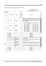
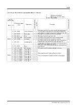
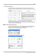
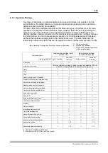
(2) #monitors
#monitors output the status of the motor and drive acquired by the drive.
They can be used to observe the conditions of the motor and drive using the
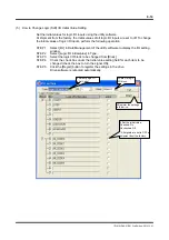
#parameter/#monitor Display, Axis Signal Monitor and Oscilloscope functions, or operate the
motor by referencing #monitor values in table data operation.
Writing to the monitors is not allowed.
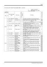
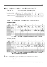
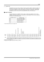
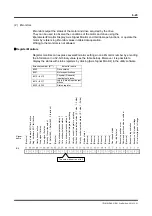
Register Monitors
Register monitors can express several #monitor settings in one #monitor number by encoding
the information in a 32-bit binary value (see the table below). Moreover, it is possible to
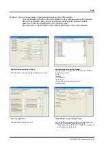
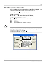
display the status with status registers by clicking [Axis Signal Monitor] in the utility software.
#monitor number (#***)
#monitor name
#300 Drive
version
#301 Motor
specifications
#310 ~ #313
Physical (Onboard)
input/output blocks
#314 ~ #317
Logic (Virtual) input/output
blocks
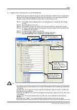
#320 ~ #322
Status register
Bit
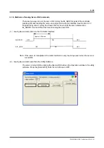
The coin window is set to 3.
(Reserve)
(Reserve)
Signal
name
Command position pulse s overflow
Excessive posit
ion erro
r
Over load status
Over speed statu
s
A
C main voltage out of rang
e
Excess
ive AC mains voltage
Pos. hardwa
re E
O
T limit active
Home sensor act
ive
Neg. har
dwar
e EOT limit active
A
rea signal 2 status
A
rea signal 1 status
Excessive regeneration
Z-pulse status
(Reserve)
(Reserve)
(Reserve)
(Reserve)
(Reserve)
(Reserve)
(Reserve)
(Reserve)
Velocity % override select
(0: Select #44, 1:
Select #45, 2: In
terlock)
Coin window selection status 2
Coin window selection status 1
Coin window selection status 0
Position control integrato
r ope
rating
Velocity control integrato
r ope
rating
Position control selection status (0: 1 side, 1: 2 side)
Velocity control selection status (0: 1 side, 1: 2 side)