


appendix1‑25
117
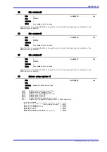
Absolute linear coordinate limit #2
This is a value used to determine the coordinate value when AC power is turned on if the linear
coordinate system is selected in a motor with absolute encoder/resolver. The processing is performed
in combination with absolute linear coordinate limit value #1.
‑99999999
99999999
depend on motor.driver type
Min:
Max:
Initial:
Unit:
Axis command unit
Only for ABS type
Initial value:
[rotation]:‑180000 [unit/rev]
[Linear] :‑500000 [unit/m]
ABS̲L̲Lmt2
Updated on power cycle
Dec
119
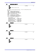
CC‑Link setup register
Bit 16 〜 24 CC‑Link allowable communication error frequency (min:1,max:500)
Bit 12 〜 14 Number of CC‑Link reconnection attempts (min:0,max:5)
Bit 7 〜 4 Baud rate (min:0,max:4)
Bit 0 Occupied Station Select (0: 1 station accupied, 1: 2 stations occupied)
CC‑Link allowable communication error frequency:
Specifies the allowable frequency of the occurrence of CC‑Link interface transmission failures.
Specify the allowable number of occurrences per second.
Number of CC‑Link reconnection attempts:
Specifies the number of reconnection attempts in case a CC‑Link interface communication error occurs.
If 0 is set, a communication error is generated once the first error accurs. If N is set, a
communication error is generated when communication fails repeatedly for N+1 times.
Baud rate:
0:156kbps
1:625kbps
2:2.5Mbps
3:5Mbps
4:10Mbps
−
−
depend on motor.driver type
Min:
Max:
Initial:
Unit:
Inital value: H00010041
CC‑Link allowable communication error frequency :1
Number of CC‑Link reconnection attempts :0
Baud rate :4
Occupied Station Select :1 2 stations occupied
CC̲LinkReg
Updated on power cycle
Hex
TI 71M01D06‑01E 2nd Edition : 2007.01.10‑00