


6-36
TI71M01D06-01EN 3rd Edition: 2012.12.01
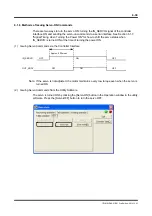
(4) Coordinate Values when Turning the Power ON
In the Case of Incremental Motors: DM/DR Series Motors
The coordinate value when turning the power ON is 0 for both command units (#376) and
pulse (#371).
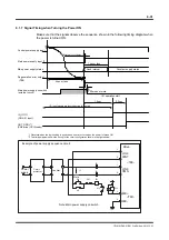
In the Case of Absolute Motors: DB Series Motors
[For Rotation Coordinates]
For both command units (#376) and pulse (#371), the coordinate value when turning the
power ON is initialized to the value normalized using [Scaling data ratio denominator (on the
command unit)] (#112) and [Scaling data ratio numerator (on the pulse)] (#113) as one
rotation, based on the value detected from the absolute encoder/resolver.
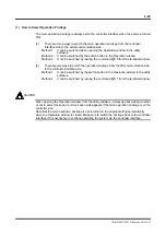
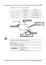
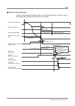
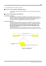
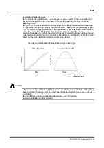
[For Linear Coordinates]
For both command units (#376) and pulse (#371), the coordinate value when turning the
power ON is initialized to the value normalized to the area (C1 - C2) defined by [Absolute
linear coordinate limit #1] (#116) and [Absolute linear coordinate limit #2] (#117) using
[Scaling data ratio denominator (on the command unit)] (#112) and [Scaling data ratio
numerator (on the pulse)] (#113) as one rotation, based on the value detected from the
absolute encoder/resolver.
If the position when the power is turned ON is the C1-B area or A-C2 area, an error that
cannot be reset other than by cycling the power will occur. Cycle the power in the C1-C2 area.
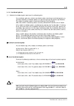
One rotation of the motor
Position B is the smaller of
#116 or #117.
Position A is the larger of #116 or #117.
Position C is the intermediate position
between position A and position B.