


appendix1‑23
110
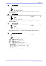
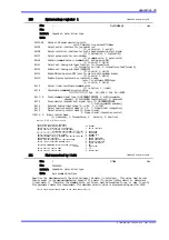
System setup register 1
Bit31‑28 Setup of AC power monitoring cycle
cycle time=(setting value+2)*10msec
Bit25 Select serial interface for jog operation
(0: controller, 1: serial)
Bit24 Select controller interface for high speed processing start signal
(0: low[Invalid], 1: high[Valid])
Bit17 Select pulse scale for coin window
(0: command units, 1: pulse units)
Bit16 Sustain command value in command unit during servo‑ON
(0: Invalid, 1: Valid)
Bit13 Select ext. Analog sub input function for torque/force
(0: torque/force limit, 1: torque/force feed forward)
Bit12 Enable ext. Analog sub input (ASUB̲IN)
(0: Invalid, 1: Valid)
Bit11 Brake‑ON during servo‑OFF (only for motors with dynamic brake)
(0: Invalid, 1: Valid)
Bit10 Enable Z‑pulse hysteresis on inaccurate edge
(only for software ZERO type)
(0: Invalid, 1: Valid)
Bit 9 Select linear coordinate command units
(0: rotation, 1: linear)
Bit 8 Coordinate commanded direction setup
(0: Pos. Dir.=CW, 1: Pos. Dir.=CCW)
Bit 7‑ 6 Pulse command signal type (0:UP‑DOWN(CW/CCW), 1: A‑B(incremental
encoder), 2: PLS‑SIGN(step/direction), 3: reserved)
Bit 5 Pulse monitor (encoder out) signal type (0: UP‑DOWN(CW/CCW),
1: A‑B(incremental encoder))
Bit 4 External analog input range (0: +/‑6V, 1: +/‑10V)
Bit 3 Select position control mode (0: I‑P, 1: Proportional integration)
Bit 2 Select velocity control mode (0: Proportional,
1: Proportional integration control)
Bit 1‑ 0 Basic control mode
(0: (reserved), 1: Torque/Force, 2: Velocity, 3: Position)
−
−
depend on motor.driver type
Min:
Max:
Initial:
Unit:
Bit13,12,7〜6,5,4,1〜0 are invalid.
Inital value: Motor/Drive dependent
Setup of AC power monitoring cycle : 15 170msec
Select serial interface for jog operation : 1 Serial interface
Select controller interface for high speed
processing start signal [CC‑Link] : 1 High speed
[other ] : 0 Slow speed
Select pulse scale for coin window : 0 Command unit
Sustain command value in command unit during servo‑ON : 0 Disalbe
Brake‑ON during servo‑OFF : 1 Enable (Brake‑ON)
Enable Z‑pulse hysteresis on inaccurate edge : 1 Enable (Hysteresis)
Select linear coordinate command units : 0 Rotation coordinate
: 1 Linear coordinate
Coordinate commanded direction setup [rotation] : 1 CW
[linear] : 1 Right side
Select position control mode : 0 I‑P
Select velocity control mode : 0 Proportional
SystemReg1
Updated on power cycle
Hex
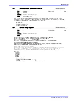
111
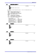
Maximum velocity limit
Specifies the maximum velocity the drive can move the motor (in units/sec). This value must be less
than or equal to the maximum mechanical speed of the motor (in rev/sec [rotary motor] or meters/sec
[linear motor]). Therefore, the command units, units/sec, must be converted to rps, or mps, to verify
this parameter meets this requirement. This maximum velocity value is displayed using monitor #305.
1
32000000
depend on motor.driver type
Min:
Max:
Initial:
Unit:
Axis command unit/sec
Initial value: Approximately equal to the rated motor velocity
Vmax
Updated on power cycle
Dec
TI 71M01D06‑01E 2nd Edition : 2007.01.10‑00