


8-18
TI71M01D06-01EN 3rd Edition: 2012.12.01
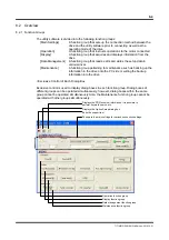
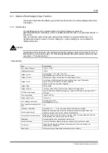
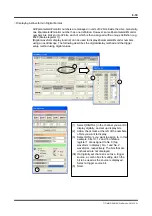
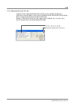
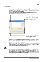
Displaying a Waveform in Digital Format
All #parameters/#monitor numbers are managed in units of 32 bits inside the drive. Generally,
one #parameter/#monitor number has one definition. However, some #parameters/#monitor
numbers are broken into 32 bits, each of which is then assigned with a unique definition (e.g.,
#320 (Status register 1)).
[Digital waveform display function] can be used to display #parameters/#monitor numbers
using an oscilloscope. The following describes the digital display method and the trigger
setup method using digital values.
1
2
3
4
5
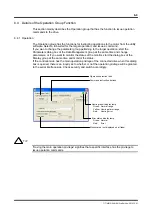
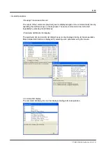
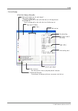
(1) Select [DIGITAL] in the channel you want to
display digitally, and set up display bits.
(2) Add a check mark at the left of the numbers
of bits you want to display.
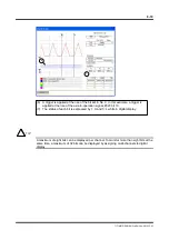
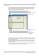
(3) Select bit No.'s you want to assign to. In this
example, bits 10, 12 and 16 of status
register 1 are assigned to No. 0 (top
waveform in display), No. 1 and No. 2
waveforms, respectively. The bits that are
unchecked are not displayed.
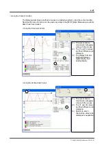
(04) If a digitally set channel is set as a trigger
source, a combo box for setting which the
bit to be used as the source is displayed.
Select a trigger source bit.
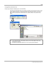
(5) Start.