


6-87
TI71M01D06-01EN 3rd Edition: 2012.12.01
(b) Homing of an Absolute Motor
The homing method is different between incremental motors (DM/DR series motors) and
absolute motors (DB series motors).
Here, only the homing method of absolute motors is described. For more information about
the homing method of incremental motors, see Section 6.4.5 (a), "Homing of an Incremental
Motor."
In homing of an absolute motor, the motor establishes a coordinate system by moving to a
position away from the motor's home position by the home offset amount, and setting the
command unit command value to the value set in parameter #57 [Coordinate value in
command units after homing] at the position to which the motor has moved.
It is possible to set the acceleration/deceleration profile for movement. Velocity override also
functions in real time.
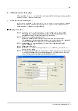
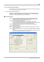
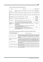
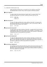
(1) How to Set Absolute Positioning Move
Set the data according to the flowchart showing the procedure for creating table data in 6.4.1,
"Table Data Operation." See the following for how to set operation data and #parameters,
corresponding to steps 4 and 6 in the flowchart.
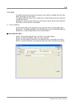
Setting Operation Data
STEP 1 Select the settling width from #parameters 90 to 97 [Coin window].
The setup value of #parameters [Coin window] can be changed by selecting
[Homing, absolute motor] in [Function parameter] of [#parameter].
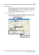
STEP 2 Set the acceleration/deceleration time.
Select the acceleration/deceleration time from #parameters (#72 to #79).
The setup value of #parameters [acceleration/deceleration time] can be changed by
selecting [Homing, absolute motor] in [Function parameter] of [#parameter].
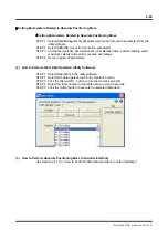
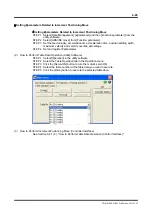
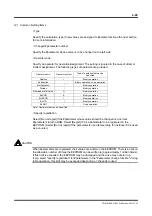
STEP 3 Select either constant acceleration or S-curved profile as the acceleration
type/deceleration type.
STEP 4 Select the movement direction type if the rotation coordinate system is chosen as
the coordinate system.