


5-4
TI 71M01D06-01EN 3rd Edition: 2012.12.01
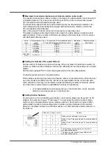
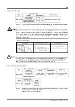
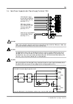
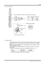
5.2 Main Power Supply/Control Power Supply Terminal <TB1>
Protective ground AWG#12
Crimp terminal : N5.5-4
(made by J.S.T.)
Control power supply
(single phase) AWG#20
Main power supply
(three phases) AWG#14
Crimp terminal: N2-4
(made by J.S.T.)
Crimp terminal: N1.25-4
(made by J.S.T.)
Make sure to perform ground in order to avoid electric shock accidents. Moreover, make sure
to connect the GND terminals of the motor and the drive.
The tightening torque of the terminal block screw is 1.8 N-m and the matching wire size is
AWG#10 to 12. If a wire whose size does not match this specification is connected to the
terminal block, be sure to use a crimp terminal of the UL or CSA standard that matches the
wire size. Use crimp tools specified by the manufacturer.
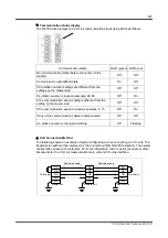
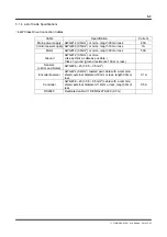
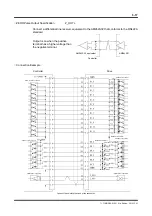
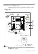
Set up a sequence circuit similar to the one shown below in order to avoid accidents where
the drive burns out in case of over-voltage errors and regeneration errors.
Line
filter
Circuit
protector
RY1
ON
OFF
MC
MC
MC
MC
RY1
Power
supply
LINE
CONT
LINE
MAIN
<TB1>
<TB4>
ERR+
ERR-
Drive
*
Keep the ON switch in the ON status until the drive enters the RDY status.
L
L
N
N
5
6
Example of power supply sequence circuit
CAUTION
!
DANGER
CAUTION