


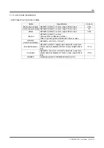


5-8
TI 71M01D06-01EN 3rd Edition: 2012.12.01
+
L
OUT
-
+
L
OUT
-
+
L
OUT
-
+
‑
1
2
COMP0
3
4
XORG
XOTD
XOTU
5
6
ERR+
ERR‑
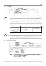
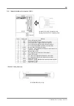
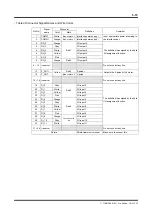
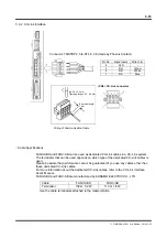
Example of sensor connection (Sensor: EE-SX670 made by Omron)
The sensor logic is connected to B-contact.
The sensor output must be set to switch OFF when the light is blocked.
The sensor of the type described above is turned off when the light is blocked by
connecting cables as shown below.
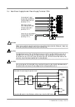
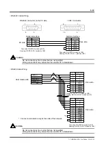
* See Section 3.2, "Main Power Supply/Control Power Supply Terminal " for more
information about wiring the regeneration alarm outputs.
DC
power supply
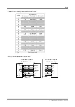
Pin No.
Signal name
Home input B-contact
- EOT input B-contact
+ EOT input B-contact
*
Regen. Resistor error output