


6-58
TI71M01D06-01EN 3rd Edition: 2012.12.01
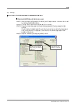
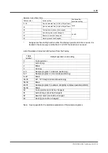
(1) I/O Signals to be Used
The I/O signals for table data operation are used to give instructions via the controller
interface. If signals have not been assigned, assign them with the hard I/O assignment
function as needed.
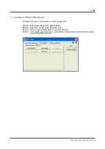
(To operate via the serial interface, proceed to (2) Table Data Setting Procedure.)
I/O
Logic I/O signal abbreviation
Logic I/O signal name
Input
IN_SERVO Servo
IN_START
Start table operation
IN_STOP
Stop table operation
IN_ABORT
Stop motion & table operation
IN_I_CODE. 0
Code input 0
IN_I_CODE. 1
Code input 1
IN_I_CODE. 2
Code input 2
IN_I_CODE. 3
Code input 3
IN_I_CODE. 4
Code input 4
IN_I_CODE. 5
Code input 5
Output
OUT_DRDY Drive
ready
OUT_SRDY Servo
ready
OUT_MODE_EXE In
operation
OUT_M_EN
Outputting M code
OUT_0_CODE. 0
Code output 0
OUT_0_CODE. 1
Code output 1
OUT_0_CODE. 2
Code output 2
OUT_0_CODE. 3
Code output 3
OUT_0_CODE. 4
Code output 4
OUT_0_CODE. 5
Code output 5