


6-10
TI71M01D06-01EN 3rd Edition: 2012.12.01
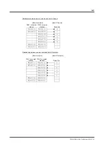
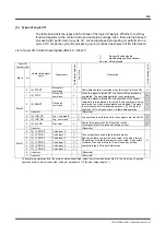
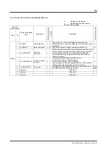
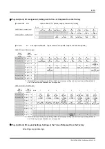
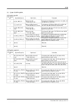
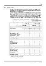
List of Logic I/O Contact Output Signals (Block 0 ~ Block 1)
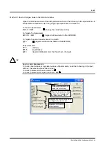
: Frequently
used
signals
Δ
:
Signals assigned as necessary
No mark: Not applicable
Logic I/O
Contact input
Abbreviated signal
name
Signal name
Table data op
era
tion
Jog move
Description
I/O pr
ocessing cycle
Block bit
Block 0
0 OUT_DRDY
Drive (CPU) ready
This signal turns ON if no error occurs after turning the power
ON. It is used in the sequence when the power is turned ON.
(see Section 6.1.7 Signal Timing when Turning the Power ON)
H
1 OUT_SRDY
Servo
ready
This signal turns ON when the servo is turned ON.
H
2 OUT_ERR
Error
This signal turns ON if an error occurs.
H
3 OUT_AXIS_EXE Axis
operating
Δ
Δ
This signal turns ON when the motor is being operated.
H
4 OUT_OVER
Over
speed
Δ
Δ
This signal turns ON if an over speed error occurs.
H
5 OUT_OVL
Overload
signal
Δ
Δ
This signal turns ON if an overload error occurs. The hard I/O
logical setting of this signal is set to "negative logic" at
shipment from the factory. In this status, the output transistor is
turned OFF if an overload error occurs.
H
6 OUT_BUSY
Busy
Δ
Δ
This signal turns ON during table operation or while executing
jog movement.
H
7 OUT_JOG_EXE Executing
jog
Δ
This signal turns ON while executing jog movement.
H
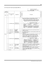
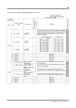
Block 1
0 OUT_O_CODE.0
Code output 0
Δ
Δ
These signals output M codes in the binary format.
OUT_M_EN is turned ON while an M code is being output.
L
1 OUT_O_CODE.1
Code output 1
Δ
Δ
2 OUT_O_CODE.2
Code output 2
Δ
Δ
3 OUT_O_CODE.3
Code output 3
Δ
Δ
4 OUT_O_CODE.4
Code output 4
Δ
Δ
5 OUT_O_CODE.5
Code output 5
Δ
Δ
6 OUT_O_CODE.6
Code output 6
Δ
Δ
7 OUT_O_CODE.7
Code output 7
Δ
Δ