


6-6
TI71M01D06-01EN 3rd Edition: 2012.12.01
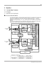
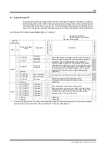
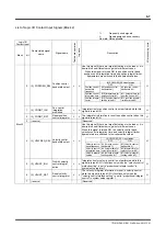
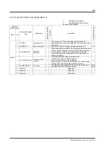
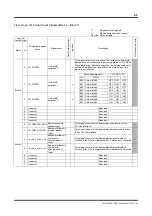
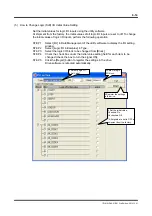
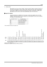
(3) Types of Logic I/O
The table below lists the types and functions of the logic I/O signals. Whether or not they
function depends on the control mode and operation privilege. Also, there are high speed
processing (H) performed in a cycle of 1 ms and low speed processing (L) performed in a
cycle of 10 ms as the cycle (I/O processing cycle) to refresh each piece of I/O information.
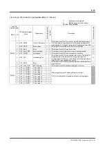
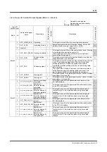
List of Logic I/O Contact Input Signals (Block 0 ~ Block 1)
: Frequently
used
signals
Δ
:
Signals assigned as necessary
No mark: Not applicable
Logic I/O
Contact input
Abbreviated signal
name
Signal name
Table data op
era
tion
Jog move
Description
I/O pr
ocessing cycle
Block bit
Block 0
0 IN_START
Drive start
command
Table data operation is started when this signal is turned ON.
H
1 IN_STOP
Drive end
command
Δ
When this signal is turned ON, the current table operation is
completed. The next table operation is not performed.
L
2 IN_ABORT
Drive end
command
Δ
When this signal is turned ON, the execution of the current
table data is immediately interrupted. If axis operation is being
performed, the motor is decelerated and stopped. This signal
is normally used for the following purposes. [1] To stop test
operation [2] To stop execution of a table data operation
L
3 (reserve)
(Reserved)
4 IN_JOG_UP
Jog + command *
Jog operation is performed while these signals are turned ON.
L
5 IN_JOG_DN
Jog - command *
6 IN_M_ANS
M
answer
Δ
Assign this signal when the M function is used.
This signal turns ON when an M answer is sent.
L
7 (reserve)
(Reserved)
Block 1
0 IN_I_CODE.0
Code input 0
These signals are used in table data operation.
Specify the table number to be executed in the binary format.
Depending on the table number to be executed, it is possible
to reduce the number of hard I/O points used by setting
appropriate logic I/O input initial values.
H
1 IN_I_CODE.1
Code input 1
2 IN_I_CODE.2
Code input 2
3 IN_I_CODE.3
Code input 3
4 IN_I_CODE.4
Code input 4
5 IN_I_CODE.5
Code input 5
6 (reserve)
(Reserved)
7 (reserve)
(Reserved)
*
To execute jog operation from the serial communication side, select "serial communication side" in the "selection of jog feed
operation serial communication side" setting of parameter #110 [System setup register 1].