


6-112
TI71M01D06-01EN 3rd Edition: 2012.12.01
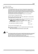
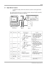
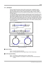
6.7 Signal Monitor Function
*
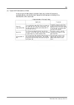
The R7041WC analog monitor card (optional) is required to use the signal monitor
function.
By using the analog monitor card, it is possible to observe velocity and monitor waveforms
generated inside the drive using an oscilloscope.
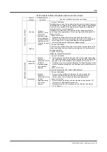
Signal
Signal name
Wiring
Output signal level
Remarks
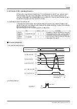
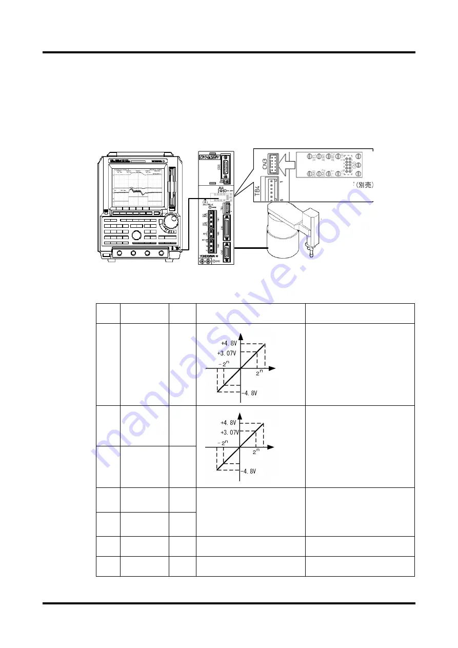
VEL Velocity
monitor
CN3-1
Output voltage [V]
This signal outputs the velocity
waveform as an analog voltage
signal. It is also possible to output
an AC-coupled waveform. The
output range can be adjusted
using the utility software.
Gain setup range
±
3.07V VS
±
2 raised to the nth power
(8
≤
n
≤
24)
Maximum output: 4.8V
AM1
Analog monitor
1
CN3-2
Output voltage [V]
These signals output selected
#parameter/#monitor values (#0 to
#427) as analog voltage signals.
The output range can be adjusted
using the utility software.
Gain setup range
±
3.07V VS
±
2 raised to the nth
power
(8
≤
n
≤
24)
Maximum output: 4.8V
AM2
Analog monitor
2
CN3-3
DM1 Digital monitor 1 CN3-4
Output voltage
If the value is 1: Approx. 5V
If the value is 0: Approx. 0V
These signals select
#parameter/#monitor values (#0 to
#427) and bit numbers, and output
as digital voltage signals.
DM2 Digital monitor 2 CN3-5
T-R
Commanded
current value
CN3-6
±
maximum current=
±
4.3V
GND Ground
CN3-10
---
This is a common ground pin for
signal monitoring.
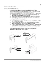
#parameter/#
monitor value
#parameter/#
monitor value
Oscilloscope
DrvPIII
Motor
Analog monitor card
(optional) R7041WC