


6-32
TI71M01D06-01EN 3rd Edition: 2012.12.01
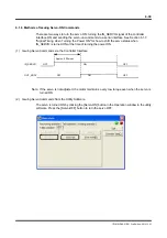
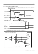
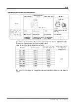
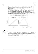
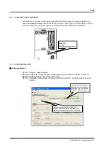
Rush interval
Constant supply status
External circuit delay
1.2sec
50 msec or more
I/O operation start
I/O input signals are ignored during this period.
Software delay
500ms
Normal operation starting
point of CN4 I/O
inputs/outputs (IN_SERVO
should be turned ON
before this timing.)
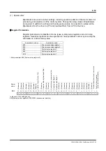
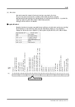
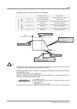
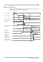
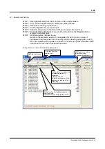
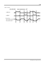
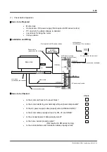
Sequence at Startup Operation
To start up using table data operation, make sure the signals observe the sequence shown in
the following timing diagram when the power is turned ON.
Main power supply input
Control power supply input
Main power supply status
Regeneration error output
(TB4)
Main power supply on switch
(external circuit)
1sec or less
IN_
(CN4 I/O input)
4sec or less
OUT_DRDY*1
(CN4 drive (CPU) ready)
IN_SERVO
(CN4 servo command)
OUT_SRDY
(CN4 servo ready)
OUT_MODE_EXE
(Executing CN4 contact output)