2-10
C70 Capacitor Bank Protection and Control System
GE Multilin
2.2 SPECIFICATIONS
2 PRODUCT DESCRIPTION
2
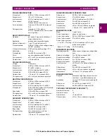
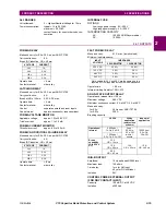
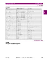
NEGATIVE SEQUENCE TOC
Pickup level:
0.000 to 30.000 pu in steps of 0.001
Dropout level:
97% to 98% of pickup
Level accuracy:
±0.5% of reading or ±0.4% of rated
(whichever is greater)
from 0.1 to 2.0 x CT rating
±1.5% of reading > 2.0 x CT rating
Curve shapes:
IEEE Moderately/Very/Extremely
Inverse; IEC (and BS) A/B/C and Short
Inverse; GE IAC Inverse, Short/Very/
Extremely Inverse; I
2
t; FlexCurves™
(programmable); Definite Time (0.01 s
base curve)
Curve multiplier (Time dial): 0.00 to 600.00 in steps of 0.01
Reset type:
Instantaneous/Timed (per IEEE) and Lin-
ear
Timing accuracy:
Operate at > 1.03
×
actual pickup
±3.5% of operate time or ±½ cycle
(whichever is greater)
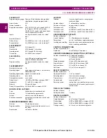
NEGATIVE SEQUENCE IOC
Pickup level:
0.000 to 30.000 pu in steps of 0.001
Dropout level:
97 to 98% of pickup
Level accuracy:
0.1 to 2.0
×
CT rating: ±0.5% of reading
or ±0.4% of rated (whichever is greater);
>
2.0
×
CT rating: ±1.5% of reading
Overreach:
<
2%
Pickup delay:
0.00 to 600.00 s in steps of 0.01
Reset delay:
0.00 to 600.00 s in steps of 0.01
Operate time:
< 20 ms at 3
×
pickup at 60 Hz
Timing accuracy:
Operate at 1.5
×
pickup
±3% or ±4 ms (whichever is greater)
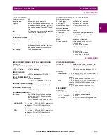
NEUTRAL DIRECTIONAL OVERCURRENT
Directionality:
Co-existing forward and reverse
Polarizing:
Voltage, Current, Dual
Polarizing voltage:
V_0 or VX
Polarizing current:
IG
Operating current:
I_0
Level sensing:
3
×
(|I_0| –
K
×
|I_1|), IG
Independent for forward and reverse
Restraint,
K
:
0.000 to 0.500 in steps of 0.001
Characteristic angle:
–90 to 90° in steps of 1
Limit angle:
40 to 90° in steps of 1, independent for
forward and reverse
Angle accuracy:
±2°
Offset impedance:
0.00 to 250.00
Ω
in steps of 0.01
Pickup level:
0.002 to 30.000 pu in steps of 0.01
Dropout level:
97 to 98%
Operation time:
< 16 ms at 3
×
pickup at 60 Hz
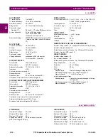
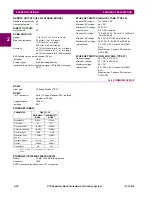
PHASE CURRENT UNBALANCE
Operation:
per phase
Auto-setting:
on demand from keypad, per phase
Number of elements:
1 per CT bank, maximum of 3
Inherent unbalance factor:–0.1000 to 0.1000 in steps of 0.0001,
per phase
Number of trip/alarm stages: 4 per phase with individual timers per
stage
Pickup threshold:
0.001 to 5.000 pu of split-phase CT nom-
inal in steps of 0.001
Pickup level accuracy:
0.002 pu for <1 pu current and <20 CT
mismatch between phase and differen-
tial CT
Hysteresis:
3% or 0.001 pu, whichever is greater
Pickup delay:
0 to 600.00 s in steps of 0.01
Time accuracy:
±3% or ±35 ms, whichever is greater
Operate time:
<35 ms at 60 Hz
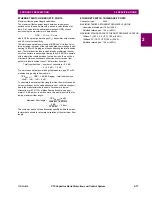
NEUTRAL CURRENT UNBALANCE
Auto-setting:
on demand from keypad
Number of elements:
1 per CT bank, to a maximum of 3
Inherent unbalance factor: magnitude of 0 to 0.1500 in steps of
0.0001, angle of 0 to 359° in steps of 1
Number of trip/alarm stages: 4, with individual timers per stage
Pickup threshold:
0.001 to 5.000 pu of ground input CT in
steps of 0.001
Pickup level accuracy:
0.002 pu for <1 pu current and < 20 CT
mismatch between phase and neutral
CT
Hysteresis:
3% or 0.001 pu, whichever is greater
Slope:
0.0 to 10.0% in steps of 0.1
Pickup delay:
0 to 600.00 s in steps of 0.01
Time accuracy:
±3% or ±35 ms, whichever is greater
Operate time:
<35 ms at 60 Hz
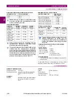
NEUTRAL VOLTAGE UNBALANCE
Operation:
compensated for inherent bank and sys-
tem unbalance
Auto-setting:
on demand from keypad
Number of elements:
1 per VT bank, maximum of 3
Compensating factor:
0.7500 to 1.2500 in steps of 0.0001
Number of trip/alarm stages: 4 with individual timers
Pickup threshold:
0.001 to 1.000 pu of nominal of the bank
neutral point VT in steps of 0.001
Slope:
0 to 10% in steps of 0.1
Pickup level accuracy:
0.002 pu for <10 VT mismatch between
phase and neutral VT
Hysteresis:
3% or 0.001 pu whichever is greater
Pickup delay:
0 to 600.00 s in steps of 0.01
Time accuracy:
±3% or ±35 ms, whichever is greater
Operate time:
<35 ms at 60 Hz
Содержание UR Series C70
Страница 2: ......
Страница 10: ...x C70 Capacitor Bank Protection and Control System GE Multilin TABLE OF CONTENTS ...
Страница 30: ...1 20 C70 Capacitor Bank Protection and Control System GE Multilin 1 5 USING THE RELAY 1 GETTING STARTED 1 ...
Страница 124: ...4 30 C70 Capacitor Bank Protection and Control System GE Multilin 4 3 FACEPLATE INTERFACE 4 HUMAN INTERFACES 4 ...
Страница 344: ...5 220 C70 Capacitor Bank Protection and Control System GE Multilin 5 10 TESTING 5 SETTINGS 5 ...
Страница 396: ...8 18 C70 Capacitor Bank Protection and Control System GE Multilin 8 3 ENERVISTA SECURITY MANAGEMENT SYSTEM 8 SECURITY 8 ...
Страница 414: ...9 18 C70 Capacitor Bank Protection and Control System GE Multilin 9 1 OVERVIEW 9 THEORY OF OPERATION 9 ...
Страница 436: ...10 22 C70 Capacitor Bank Protection and Control System GE Multilin 10 4 SETTING EXAMPLE 10 APPLICATION OF SETTINGS 10 ...
Страница 547: ...GE Multilin C70 Capacitor Bank Protection and Control System B 79 APPENDIX B B 4 MEMORY MAPPING B ...
Страница 548: ...B 80 C70 Capacitor Bank Protection and Control System GE Multilin B 4 MEMORY MAPPING APPENDIXB B ...
Страница 586: ...D 10 C70 Capacitor Bank Protection and Control System GE Multilin D 1 OVERVIEW APPENDIXD D ...
Страница 598: ...E 12 C70 Capacitor Bank Protection and Control System GE Multilin E 2 DNP POINT LISTS APPENDIXE E ...

