10-2
C70 Capacitor Bank Protection and Control System
GE Multilin
10.1 ARRANGEMENT OF SHUNT CAPACITOR BANKS
10 APPLICATION OF SETTINGS
10
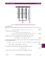
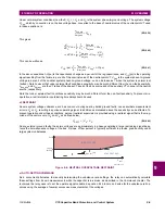
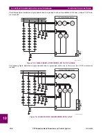
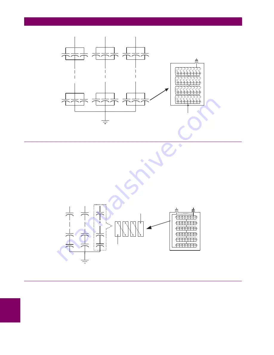
Figure 10–2: INTERNALLY FUSED SHUNT CAPACITOR BANK AND CAPACITOR UNIT
10.1.4 FUSELESS CAPACITORS
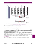
Fuseless capacitor bank are typically the most prevalent designs. The capacitor units for fuseless capacitor banks are con-
nected in series strings between phase and neutral. The higher the bank voltage, the more capacitor elements in series.
The expected failure of the capacitor unit element is a short circuit, where the remaining capacitor elements will absorb the
additional voltage. For example, if there are 6 capacitor units in series and each unit has 8 element groups in series there is
a total of 48 element groups in the string. If one capacitor element fails, this element is shorted and the voltage across the
remaining elements is 48 / 47 of the previous value, or about 2% higher. The capacitor bank remains in service; however,
successive failures of elements would aggravate the problem and eventually lead to the removal of the bank.
The fuseless design is usually applied for applications at or above 34.5 kV where each string has more than ten elements
in series to ensure the remaining elements do not exceed 110% rating if an element in the string shorts.
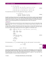
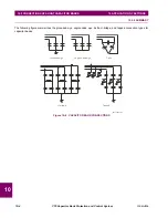
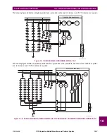
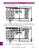
Figure 10–3: FUSELESS SHUNT CAPACITOR BANK AND SERIES STRING
10.1.5 UNFUSED CAPACITORS
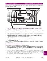
Contrary to the fuseless configuration, where the units are connected in series, the unfused shunt capacitor bank uses a
series or parallel connection of the capacitor units. The unfused approach would normally be used on banks below 34.5 kV,
where series strings of capacitor units are not practical, or on higher voltage banks with modest parallel energy. This design
does not require as many capacitor units in parallel as an externally fused bank.
phase
A
phase
B
phase
C
834754A1.CDR
834755A1.CDR
Содержание UR Series C70
Страница 2: ......
Страница 10: ...x C70 Capacitor Bank Protection and Control System GE Multilin TABLE OF CONTENTS ...
Страница 30: ...1 20 C70 Capacitor Bank Protection and Control System GE Multilin 1 5 USING THE RELAY 1 GETTING STARTED 1 ...
Страница 124: ...4 30 C70 Capacitor Bank Protection and Control System GE Multilin 4 3 FACEPLATE INTERFACE 4 HUMAN INTERFACES 4 ...
Страница 344: ...5 220 C70 Capacitor Bank Protection and Control System GE Multilin 5 10 TESTING 5 SETTINGS 5 ...
Страница 396: ...8 18 C70 Capacitor Bank Protection and Control System GE Multilin 8 3 ENERVISTA SECURITY MANAGEMENT SYSTEM 8 SECURITY 8 ...
Страница 414: ...9 18 C70 Capacitor Bank Protection and Control System GE Multilin 9 1 OVERVIEW 9 THEORY OF OPERATION 9 ...
Страница 436: ...10 22 C70 Capacitor Bank Protection and Control System GE Multilin 10 4 SETTING EXAMPLE 10 APPLICATION OF SETTINGS 10 ...
Страница 547: ...GE Multilin C70 Capacitor Bank Protection and Control System B 79 APPENDIX B B 4 MEMORY MAPPING B ...
Страница 548: ...B 80 C70 Capacitor Bank Protection and Control System GE Multilin B 4 MEMORY MAPPING APPENDIXB B ...
Страница 586: ...D 10 C70 Capacitor Bank Protection and Control System GE Multilin D 1 OVERVIEW APPENDIXD D ...
Страница 598: ...E 12 C70 Capacitor Bank Protection and Control System GE Multilin E 2 DNP POINT LISTS APPENDIXE E ...


