


B-76
C70 Capacitor Bank Protection and Control System
GE Multilin
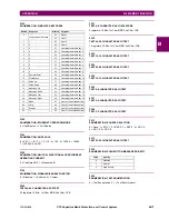
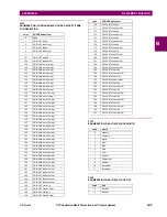
B.4 MEMORY MAPPING
APPENDIX B
B
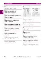
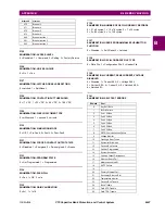
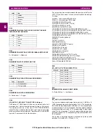
F239
ENUMERATION: REAL TIME CLOCK DAYLIGHT SAVINGS
TIME START DAY INSTANCE
F241
ENUMERATION: NEUTRAL VOLTAGE UNBALANCE BUS 3V0
0 = Calculated, 1 = Measured
F254
ENUMERATION: TEST MODE FUNCTION
F255
ENUMERATION: CAPACITOR BANK GROUNDING
F260
ENUMERATION: DATA LOGGER MODE
0 = Continuous, 1 = Trigger
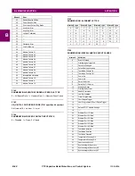
F300
UR_UINT16: FLEXLOGIC™ BASE TYPE (6-bit type)
The FlexLogic™ BASE type is 6 bits and is combined with a 9 bit
descriptor and 1 bit for protection element to form a 16 bit value.
The combined bits are of the form: PTTTTTTDDDDDDDDD,
where P bit if set, indicates that the FlexLogic™ type is associated
with a protection element state and T represents bits for the BASE
type, and D represents bits for the descriptor.
The values in square brackets indicate the base type with P prefix
[PTTTTTT] and the values in round brackets indicate the descrip-
tor range.
[0] Off(0) – this is boolean FALSE value
[0] On (1) – this is boolean TRUE value
[2] CONTACT INPUTS (1 to 96)
[3] CONTACT INPUTS OFF (1 to 96)
[4] VIRTUAL INPUTS (1 to 64)
[6] VIRTUAL OUTPUTS (1 to 96)
[10] CONTACT OUTPUTS VOLTAGE DETECTED (1 to 64)
[11] CONTACT OUTPUTS VOLTAGE OFF DETECTED (1 to 64)
[12] CONTACT OUTPUTS CURRENT DETECTED (1 to 64)
[13] CONTACT OUTPUTS CURRENT OFF DETECTED (1 to 64)
[14] REMOTE INPUTS (1 to 32)
[28] INSERT (via keypad only)
[32] END
[34] NOT (1 INPUT)
[36] 2 INPUT XOR (0)
[38] LATCH SET/RESET (2 inputs)
[40] OR (2 to 16 inputs)
[42] AND (2 to 16 inputs)
[44] NOR (2 to 16 inputs)
[46] NAND (2 to 16 inputs)
[48] TIMER (1 to 32)
[50] ASSIGN VIRTUAL OUTPUT (1 to 96)
[52] SELF-TEST ERROR (see F141 for range)
[56] ACTIVE SETTING GROUP (1 to 6)
[62] MISCELLANEOUS EVENTS (see F146 for range)
[64 to 127] ELEMENT STATES
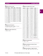
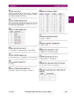
F400
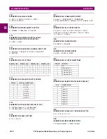
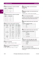
UR_UINT16: CT/VT BANK SELECTION
F491
ENUMERATION: ANALOG INPUT MODE
0 = Default Value, 1 = Last Known
F500
UR_UINT16: PACKED BITFIELD
First register indicates input/output state with bits 0 (MSB) to 15
(LSB) corresponding to input/output state 1 to 16. The second reg-
ister indicates input/output state with bits 0 to 15 corresponding to
input/output state 17 to 32 (if required) The third register indicates
input/output state with bits 0 to 15 corresponding to input/output
state 33 to 48 (if required). The fourth register indicates input/out-
put state with bits 0 to 15 corresponding to input/output state 49 to
64 (if required).
The number of registers required is determined by the specific
data item. A bit value of 0 = Off and 1 = On.
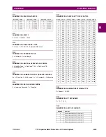
2
Tuesday
3
Wednesday
4
Thursday
5
Friday
6
Saturday
value
instance
0
First
1
Second
2
Third
3
Fourth
4
Last
Value
Function
0
Disabled
1
Isolated
2
Forcible
Value
Description
0
VT (ungrounded)
1
CTxR (grounded
value
day
bitmask
bank selection
0
Card 1 Contact 1 to 4
1
Card 1 Contact 5 to 8
2
Card 2 Contact 1 to 4
3
Card 2 Contact 5 to 8
4
Card 3 Contact 1 to 4
5
Card 3 Contact 5 to 8
Содержание UR Series C70
Страница 2: ......
Страница 10: ...x C70 Capacitor Bank Protection and Control System GE Multilin TABLE OF CONTENTS ...
Страница 30: ...1 20 C70 Capacitor Bank Protection and Control System GE Multilin 1 5 USING THE RELAY 1 GETTING STARTED 1 ...
Страница 124: ...4 30 C70 Capacitor Bank Protection and Control System GE Multilin 4 3 FACEPLATE INTERFACE 4 HUMAN INTERFACES 4 ...
Страница 344: ...5 220 C70 Capacitor Bank Protection and Control System GE Multilin 5 10 TESTING 5 SETTINGS 5 ...
Страница 396: ...8 18 C70 Capacitor Bank Protection and Control System GE Multilin 8 3 ENERVISTA SECURITY MANAGEMENT SYSTEM 8 SECURITY 8 ...
Страница 414: ...9 18 C70 Capacitor Bank Protection and Control System GE Multilin 9 1 OVERVIEW 9 THEORY OF OPERATION 9 ...
Страница 436: ...10 22 C70 Capacitor Bank Protection and Control System GE Multilin 10 4 SETTING EXAMPLE 10 APPLICATION OF SETTINGS 10 ...
Страница 547: ...GE Multilin C70 Capacitor Bank Protection and Control System B 79 APPENDIX B B 4 MEMORY MAPPING B ...
Страница 548: ...B 80 C70 Capacitor Bank Protection and Control System GE Multilin B 4 MEMORY MAPPING APPENDIXB B ...
Страница 586: ...D 10 C70 Capacitor Bank Protection and Control System GE Multilin D 1 OVERVIEW APPENDIXD D ...
Страница 598: ...E 12 C70 Capacitor Bank Protection and Control System GE Multilin E 2 DNP POINT LISTS APPENDIXE E ...


