GE Multilin
C70 Capacitor Bank Protection and Control System
B-11
APPENDIX B
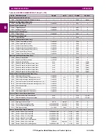
B.4 MEMORY MAPPING
B
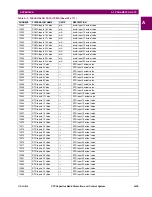
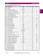
180D
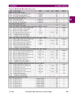
Source 1 Phase B Current Angle
-359.9 to 0
degrees
0.1
F002
0
180E
Source 1 Phase C Current Magnitude
0 to 999999.999
A
0.001
F060
0
1810
Source 1 Phase C Current Angle
-359.9 to 0
degrees
0.1
F002
0
1811
Source 1 Neutral Current Magnitude
0 to 999999.999
A
0.001
F060
0
1813
Source 1 Neutral Current Angle
-359.9 to 0
degrees
0.1
F002
0
1814
Source 1 Ground Current RMS
0 to 999999.999
A
0.001
F060
0
1816
Source 1 Ground Current Magnitude
0 to 999999.999
A
0.001
F060
0
1818
Source 1 Ground Current Angle
-359.9 to 0
degrees
0.1
F002
0
1819
Source 1 Zero Sequence Current Magnitude
0 to 999999.999
A
0.001
F060
0
181B
Source 1 Zero Sequence Current Angle
-359.9 to 0
degrees
0.1
F002
0
181C
Source 1 Positive Sequence Current Magnitude
0 to 999999.999
A
0.001
F060
0
181E
Source 1 Positive Sequence Current Angle
-359.9 to 0
degrees
0.1
F002
0
181F
Source 1 Negative Sequence Current Magnitude
0 to 999999.999
A
0.001
F060
0
1821
Source 1 Negative Sequence Current Angle
-359.9 to 0
degrees
0.1
F002
0
1822
Source 1 Differential Ground Current Magnitude
0 to 999999.999
A
0.001
F060
0
1824
Source 1 Differential Ground Current Angle
-359.9 to 0
degrees
0.1
F002
0
1825
Reserved (27 items)
---
---
---
F001
0
1840
...Repeated for Source 2
1880
...Repeated for Source 3
18C0
...Repeated for Source 4
1900
...Repeated for Source 5
1940
...Repeated for Source 6
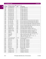
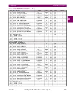
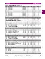
Source Voltage (Read Only) (6 modules)
1A00
Source 1 Phase AG Voltage RMS
V
F060
0
1A02
Source 1 Phase BG Voltage RMS
V
F060
0
1A04
Source 1 Phase CG Voltage RMS
V
F060
0
1A06
Source 1 Phase AG Voltage Magnitude
0 to 999999.999
V
0.001
F060
0
1A08
Source 1 Phase AG Voltage Angle
-359.9 to 0
degrees
0.1
F002
0
1A09
Source 1 Phase BG Voltage Magnitude
0 to 999999.999
V
0.001
F060
0
1A0B
Source 1 Phase BG Voltage Angle
-359.9 to 0
degrees
0.1
F002
0
1A0C
Source 1 Phase CG Voltage Magnitude
0 to 999999.999
V
0.001
F060
0
1A0E
Source 1 Phase CG Voltage Angle
-359.9 to 0
degrees
0.1
F002
0
1A0F
Source 1 Phase AB or AC Voltage RMS
0 to 999999.999
V
0.001
F060
0
1A11
Source 1 Phase BC or BA Voltage RMS
0 to 999999.999
V
0.001
F060
0
1A13
Source 1 Phase CA or CB Voltage RMS
0 to 999999.999
V
0.001
F060
0
1A15
Source 1 Phase AB or AC Voltage Magnitude
0 to 999999.999
V
0.001
F060
0
1A17
Source 1 Phase AB or AC Voltage Angle
-359.9 to 0
degrees
0.1
F002
0
1A18
Source 1 Phase BC or BA Voltage Magnitude
0 to 999999.999
V
0.001
F060
0
1A1A
Source 1 Phase BC or BA Voltage Angle
-359.9 to 0
degrees
0.1
F002
0
1A1B
Source 1 Phase CA or CB Voltage Magnitude
0 to 999999.999
V
0.001
F060
0
1A1D
Source 1 Phase CA or CB Voltage Angle
-359.9 to 0
degrees
0.1
F002
0
1A1E
Source 1 Auxiliary Voltage RMS
V
F060
0
1A20
Source 1 Auxiliary Voltage Magnitude
0 to 999999.999
V
0.001
F060
0
1A22
Source 1 Auxiliary Voltage Angle
-359.9 to 0
degrees
0.1
F002
0
1A23
Source 1 Zero Sequence Voltage Magnitude
0 to 999999.999
V
0.001
F060
0
1A25
Source 1 Zero Sequence Voltage Angle
-359.9 to 0
degrees
0.1
F002
0
1A26
Source 1 Positive Sequence Voltage Magnitude
0 to 999999.999
V
0.001
F060
0
1A28
Source 1 Positive Sequence Voltage Angle
-359.9 to 0
degrees
0.1
F002
0
1A29
Source 1 Negative Sequence Voltage Magnitude
0 to 999999.999
V
0.001
F060
0
1A2B
Source 1 Negative Sequence Voltage Angle
-359.9 to 0
degrees
0.1
F002
0
1A2C
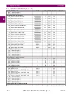
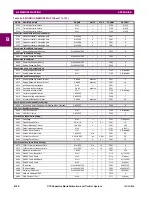
Reserved (20 items)
---
---
---
F001
0
1A40
...Repeated for Source 2
1A80
...Repeated for Source 3
1AC0
...Repeated for Source 4
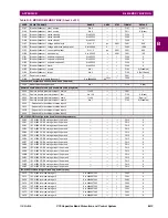
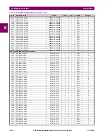
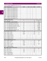
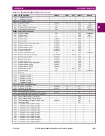
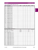
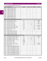
Table B–9: MODBUS MEMORY MAP (Sheet 4 of 53)
ADDR
REGISTER NAME
RANGE
UNITS
STEP
FORMAT
DEFAULT
Содержание UR Series C70
Страница 2: ......
Страница 10: ...x C70 Capacitor Bank Protection and Control System GE Multilin TABLE OF CONTENTS ...
Страница 30: ...1 20 C70 Capacitor Bank Protection and Control System GE Multilin 1 5 USING THE RELAY 1 GETTING STARTED 1 ...
Страница 124: ...4 30 C70 Capacitor Bank Protection and Control System GE Multilin 4 3 FACEPLATE INTERFACE 4 HUMAN INTERFACES 4 ...
Страница 344: ...5 220 C70 Capacitor Bank Protection and Control System GE Multilin 5 10 TESTING 5 SETTINGS 5 ...
Страница 396: ...8 18 C70 Capacitor Bank Protection and Control System GE Multilin 8 3 ENERVISTA SECURITY MANAGEMENT SYSTEM 8 SECURITY 8 ...
Страница 414: ...9 18 C70 Capacitor Bank Protection and Control System GE Multilin 9 1 OVERVIEW 9 THEORY OF OPERATION 9 ...
Страница 436: ...10 22 C70 Capacitor Bank Protection and Control System GE Multilin 10 4 SETTING EXAMPLE 10 APPLICATION OF SETTINGS 10 ...
Страница 547: ...GE Multilin C70 Capacitor Bank Protection and Control System B 79 APPENDIX B B 4 MEMORY MAPPING B ...
Страница 548: ...B 80 C70 Capacitor Bank Protection and Control System GE Multilin B 4 MEMORY MAPPING APPENDIXB B ...
Страница 586: ...D 10 C70 Capacitor Bank Protection and Control System GE Multilin D 1 OVERVIEW APPENDIXD D ...
Страница 598: ...E 12 C70 Capacitor Bank Protection and Control System GE Multilin E 2 DNP POINT LISTS APPENDIXE E ...

