GE Multilin
C70 Capacitor Bank Protection and Control System
10-15
10 APPLICATION OF SETTINGS
10.4 SETTING EXAMPLE
10
(EQ 10.13)
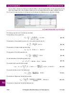
The voltage distribution factor for the healthy perfectly balanced bank for the 87V-2 and 87V-3 elements:
(EQ 10.14)
The impedance of the string for the failed capacitors elements (for one failed element,
n
f
= 1:
(EQ 10.15)
The voltage at the tap in the section with one failed capacitor element in the string:
(EQ 10.16)
The overvoltage at the affected capacitors with one capacitor element failed:
(EQ 10.17)
The differential voltage between two taps with one failed capacitor element in the upper string, assuming
K
= 1, in per-unit
values is:
(EQ 10.18)
The differential voltage between two taps with one failed capacitor element in the upper string, assuming
K
= 1, for 87V-1 in
per-unit values is:
(EQ 10.19)
The unbalance current in the window type CT between two strings with one failed capacitor element in the upper string:
(EQ 10.20)
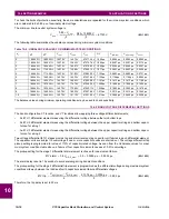
The following table summarizes the calculated values for the number of failed capacitors used to set the protection ele-
ments.
Table 10–1: UNBALANCE VALUES FOR MAXIMUM SYSTEM CONDITIONS
0
1894.42
Ω
1894.42
Ω
175.37 V
175.37 V
81340.00 V
1.000 pu
0.0000 pu
0.0000 pu
0.0000 pu
1
1894.42
Ω
1849.41
Ω
175.37 V
179.64 V
81335.73 V
1.024 pu
0.0249 pu
0.0249 pu
0.0209 pu
2
1894.42
Ω
1804.40
Ω
175.37 V
184.12 V
81331.25 V
1.050 pu
0.0510 pu
0.0510 pu
0.0429 pu
3
1894.42
Ω
1759.39
Ω
175.37 V
188.83 V
81326.54 V
1.077 pu
0.0785 pu
0.0785 pu
0.0660 pu
4
1894.42
Ω
1714.38
Ω
175.37 V
193.79 V
81321.58 V
1.105 pu
0.1074 pu
0.1074 pu
0.0904 pu
5
1894.42
Ω
1669.38
Ω
175.37 V
199.01 V
81316.36 V
1.135 pu
0.1379 pu
0.1379 pu
0.1160 pu
6
1894.42
Ω
1624.37
Ω
175.37 V
204.52 V
81310.85 V
1.167 pu
0.1701 pu
0.1701 pu
0.1431 pu
7
1894.42
Ω
1579.36
Ω
175.37 V
210.35 V
81305.02 V
1.200 pu
0.2041 pu
0.2041 pu
0.1717 pu
8
1894.42
Ω
1534.35
Ω
175.37 V
216.52 V
81298.85 V
1.235 pu
0.2401 pu
0.2401 pu
0.2020 pu
9
1894.42
Ω
1489.34
Ω
175.37 V
223.07 V
81292.30 V
1.273 pu
0.2783 pu
0.2783 pu
0.2341 pu
10
1894.42
Ω
1444.34
Ω
175.37 V
230.02 V
81285.35 V
1.313 pu
0.3188 pu
0.3188 pu
0.2682 pu
V
bottom
V
max
Z
C
b
×
Z
C
t
--------------------------
81515.37 V
4.08
Ω
×
1984.42
Ω
--------------------------------------------------------
175.37 V
=
=
=
K
tap
V
top
V
bottom
-------------------
81340.40 V
175.37 V
-------------------------------
463.8194
=
=
=
Z
C
sf
Z
C
e
N
n
×
n
f
–
(
)
Z
C
b
+
45.01
Ω
7
6
×
1
–
(
)
4.08
Ω
+
×
1849.41
Ω
=
=
=
V
tap
2
V
max
Z
C
b
×
Z
C
sf
--------------------------
81515.37 V
4.08
Ω
×
4.08
Ω
--------------------------------------------------------
179.64 V
=
=
=
OV
V
f top
(
)
N
n
×
×
V
top
N
n
×
n
f
–
(
)
×
-----------------------------------------------
81335.74 V
7
×
6
×
81340.40 V
7
6
×
1
–
(
)
×
----------------------------------------------------------------
1.024 pu
=
=
=
V
diff tap
(
)
V
tap
1
K
tap
V
tap
2
×
–
VT
nom tap
(
)
---------------------------------------------------
175.374 V
1
179.64 V
×
–
171.59 V
-------------------------------------------------------------------
0.0249 pu
=
=
=
V
diff string
(
)
V
f top
(
)
K
string
V
tap
2
×
–
VT
nom bus
(
)
-----------------------------------------------------------
175.374 V
463.8194
179.64 V
×
–
79674.34 V
-----------------------------------------------------------------------------------------
0.0249 pu
=
=
=
I
unbal
V
max
Z
C
sf
CT
tap
×
-----------------------------
V
max
Z
C
s
CT
tap
×
----------------------------
–
81515.37 V
1845.33
Ω
50
×
---------------------------------------
81515.37 V
1890.34
Ω
50
×
---------------------------------------
–
0.0209 pu
=
=
=
n
f
Z
C
s
Z
C
sf
V
tap
1
V
tap
2
V
top
OV
V
diff tap
(
)
V
diff string
(
)
I
unbal
Содержание UR Series C70
Страница 2: ......
Страница 10: ...x C70 Capacitor Bank Protection and Control System GE Multilin TABLE OF CONTENTS ...
Страница 30: ...1 20 C70 Capacitor Bank Protection and Control System GE Multilin 1 5 USING THE RELAY 1 GETTING STARTED 1 ...
Страница 124: ...4 30 C70 Capacitor Bank Protection and Control System GE Multilin 4 3 FACEPLATE INTERFACE 4 HUMAN INTERFACES 4 ...
Страница 344: ...5 220 C70 Capacitor Bank Protection and Control System GE Multilin 5 10 TESTING 5 SETTINGS 5 ...
Страница 396: ...8 18 C70 Capacitor Bank Protection and Control System GE Multilin 8 3 ENERVISTA SECURITY MANAGEMENT SYSTEM 8 SECURITY 8 ...
Страница 414: ...9 18 C70 Capacitor Bank Protection and Control System GE Multilin 9 1 OVERVIEW 9 THEORY OF OPERATION 9 ...
Страница 436: ...10 22 C70 Capacitor Bank Protection and Control System GE Multilin 10 4 SETTING EXAMPLE 10 APPLICATION OF SETTINGS 10 ...
Страница 547: ...GE Multilin C70 Capacitor Bank Protection and Control System B 79 APPENDIX B B 4 MEMORY MAPPING B ...
Страница 548: ...B 80 C70 Capacitor Bank Protection and Control System GE Multilin B 4 MEMORY MAPPING APPENDIXB B ...
Страница 586: ...D 10 C70 Capacitor Bank Protection and Control System GE Multilin D 1 OVERVIEW APPENDIXD D ...
Страница 598: ...E 12 C70 Capacitor Bank Protection and Control System GE Multilin E 2 DNP POINT LISTS APPENDIXE E ...

