10-14
C70 Capacitor Bank Protection and Control System
GE Multilin
10.4 SETTING EXAMPLE
10 APPLICATION OF SETTINGS
10
•
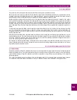
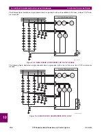
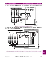
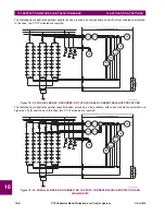
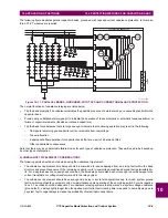
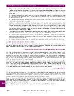
Source 2 (tap 1) and source 3 (tap 2) are assigned with the VT banks and split window CT bank connected to the tap
point of two strings of the bank, providing a signal source for the voltage differential and phase unbalance functions.
The CT and VT connections shown in the figure above are assigned the following values in EnerVista UR Setup.
10.4.4 BANK UNBALANCE CALCULATIONS
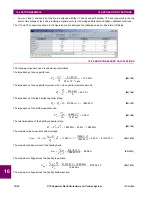
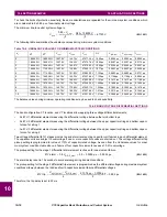
The following values are used in unbalance calculations.
The impedance of one capacitor can:
(EQ 10.5)
The impedance of one capacitor element, with
n
= 6 capacitor elements per can:
(EQ 10.6)
The impedance of the top healthy capacitor string:
(EQ 10.7)
The impedance of the bottom capacitor can:
(EQ 10.8)
The total impedance of the healthy capacitor string:
(EQ 10.9)
The maximum line-to-neutral system voltage:
(EQ 10.10)
The maximum phase current of the healthy bank:
(EQ 10.11)
The maximum voltage across the healthy top section:
(EQ 10.12)
The maximum voltage across the healthy bottom section:
Z
C
c
V
C
2
Q
C
--------
11.62 V
(
)
2
500
10
3
–
×
vars
-----------------------------------------
270.05
Ω
=
=
=
Z
C
e
Z
C
c
n
-------
270.05
Ω
6
-----------------------
45.01
Ω
=
=
=
Z
C
s
Z
C
c
N
×
270.05
Ω
7
×
1890.35
Ω
=
=
=
Z
C
b
V
CN
2
Q
C
-----------
0.825 V
(
)
2
0.167 var
----------------------------
4.08
Ω
=
=
=
Z
C
t
Z
C
s
Z
C
b
+
1890.35
Ω
4.08
Ω
+
1984.42
Ω
=
=
=
V
max
V
C
N
×
V
C
N
×
Z
C
s
------------------
Z
C
b
×
+
11620 V
7
×
11620 V
7
×
1890.35
Ω
--------------------------------
4.08
Ω
×
+
81515.37 V
=
=
=
I
max
V
max
Z
C
t
2
⁄
--------------
81515.37 V
1984.42
Ω
2
⁄
----------------------------------
86.06 A
=
=
=
V
top
V
max
Z
C
s
×
Z
C
t
--------------------------
81515.37 V
1890.35
Ω
×
1984.42
Ω
----------------------------------------------------------------
81340.40 V
=
=
=
Содержание UR Series C70
Страница 2: ......
Страница 10: ...x C70 Capacitor Bank Protection and Control System GE Multilin TABLE OF CONTENTS ...
Страница 30: ...1 20 C70 Capacitor Bank Protection and Control System GE Multilin 1 5 USING THE RELAY 1 GETTING STARTED 1 ...
Страница 124: ...4 30 C70 Capacitor Bank Protection and Control System GE Multilin 4 3 FACEPLATE INTERFACE 4 HUMAN INTERFACES 4 ...
Страница 344: ...5 220 C70 Capacitor Bank Protection and Control System GE Multilin 5 10 TESTING 5 SETTINGS 5 ...
Страница 396: ...8 18 C70 Capacitor Bank Protection and Control System GE Multilin 8 3 ENERVISTA SECURITY MANAGEMENT SYSTEM 8 SECURITY 8 ...
Страница 414: ...9 18 C70 Capacitor Bank Protection and Control System GE Multilin 9 1 OVERVIEW 9 THEORY OF OPERATION 9 ...
Страница 436: ...10 22 C70 Capacitor Bank Protection and Control System GE Multilin 10 4 SETTING EXAMPLE 10 APPLICATION OF SETTINGS 10 ...
Страница 547: ...GE Multilin C70 Capacitor Bank Protection and Control System B 79 APPENDIX B B 4 MEMORY MAPPING B ...
Страница 548: ...B 80 C70 Capacitor Bank Protection and Control System GE Multilin B 4 MEMORY MAPPING APPENDIXB B ...
Страница 586: ...D 10 C70 Capacitor Bank Protection and Control System GE Multilin D 1 OVERVIEW APPENDIXD D ...
Страница 598: ...E 12 C70 Capacitor Bank Protection and Control System GE Multilin E 2 DNP POINT LISTS APPENDIXE E ...


