viii
C70 Capacitor Bank Protection and Control System
GE Multilin
INDEX
TOC
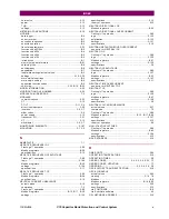
ground ......................................................................... 5-141
neutral ......................................................................... 5-129
phase .......................................................................... 5-121
specifications ................................................................... 2-9
TRACEABILITY
data .................................................... 4-11, 4-12, 8-13, 8-14
overview ............................................................... 4-10, 8-12
rules ..................................................................... 4-12, 8-14
TRACKING FREQUENCY ........................................ 6-18, B-33
TRANSDUCER I/O
actual values ................................................................. 6-19
settings .............................................................5-211, 5-212
specifications ................................................................. 2-14
wiring ............................................................................ 3-21
TRIP BUS
FlexLogic™ operands .................................................... 5-91
Modbus registers ...........................................................B-35
settings ....................................................................... 5-162
TRIP LEDs ....................................................................... 5-44
TROUBLE INDICATOR .............................................. 1-17, 7-8
U
UL APPROVAL ................................................................. 2-20
UNAUTHORIZED ACCESS
commands ..................................................................... 5-14
resetting .......................................................................... 7-6
UNDERVOLTAGE
phase ................................................................. 2-11, 5-145
UNDERVOLTAGE CHARACTERISTICS .......................... 5-144
UNEXPECTED RESTART ERROR .................................... 7-12
UNIT NOT PROGRAMMED ........................................ 5-63, 7-9
UNPACKING THE RELAY ................................................... 1-1
UNRETURNED MESSAGES ALARM ................................. 5-62
UPDATING ORDER CODE ................................................. 7-7
URPC
see entry for ENERVISTA UR SETUP
USER-DEFINABLE DISPLAYS
example ........................................................................ 5-55
invoking and scrolling .................................................... 5-53
Modbus registers ..................................................B-18, B-23
settings ................................................................ 5-53, 5-55
specifications ................................................................. 2-12
USER-PROGRAMMABLE FAULT REPORT
actual values ................................................................. 6-20
clearing .................................................................. 5-14, 7-6
Modbus registers ...........................................................B-14
settings ......................................................................... 5-37
USER-PROGRAMMABLE LEDs
custom labeling ............................................................. 4-21
defaults ......................................................................... 4-16
description ............................................................ 4-15, 4-16
Modbus registers ...........................................................B-21
settings ......................................................................... 5-44
specifications ................................................................. 2-12
USER-PROGRAMMABLE PUSHBUTTONS
FlexLogic™ operands .................................................... 5-93
Modbus registers ..................................................B-24, B-32
settings ......................................................................... 5-47
specifications .................................................................2-12
USER-PROGRAMMABLE SELF TESTS
Modbus registers ........................................................... B-22
settings ..........................................................................5-45
USERST-1 BIT PAIR ....................................................... 5-205
V
VIBRATION TESTING .......................................................2-19
VIRTUAL INPUTS
actual values ................................................................... 6-3
commands ...................................................................... 7-6
FlexLogic™ operands .....................................................5-92
logic ............................................................................ 5-198
Modbus registers .................................................... B-8, B-49
settings ........................................................................ 5-198
VIRTUAL OUTPUTS
actual values ................................................................... 6-4
FlexLogic™ operands .....................................................5-92
Modbus registers ........................................................... B-50
settings ........................................................................ 5-201
VOLTAGE BANKS ............................................................5-66
VOLTAGE DEVIATIONS ...................................................2-19
VOLTAGE DIFFERENTIAL
actual values ..................................................................6-17
commands ...................................................................... 7-2
FlexLogic™ operands .....................................................5-91
Modbus registers ......................................... B-15, B-17, B-40
settings ........................................................................ 5-150
specifications .................................................................. 2-9
theory of operation .......................................................... 9-3
VOLTAGE ELEMENTS .................................................... 5-144
VOLTAGE HARMONICS ...................................................6-16
VOLTAGE METERING
Modbus registers ........................................................... B-11
specifications .................................................................2-13
values ............................................................................6-13
VOLTAGE RESTRAINT CHARACTERISTIC ..................... 5-121
VT FUSE FAILURE
logic ............................................................................ 5-195
Modbus registers ........................................................... B-41
settings ........................................................................ 5-194
VT INPUTS ....................................................... 3-12, 5-6, 5-66
VT WIRING ......................................................................3-12
VTFF
FlexLogic™ operands .....................................................5-90
see VT FUSE FAILURE
W
WARRANTY ...................................................................... F-8
WEB SERVER PROTOCOL ...............................................5-32
WEBSITE .......................................................................... 1-1
Z
ZERO SEQUENCE CORE BALANCE .................................3-12
Содержание UR Series C70
Страница 2: ......
Страница 10: ...x C70 Capacitor Bank Protection and Control System GE Multilin TABLE OF CONTENTS ...
Страница 30: ...1 20 C70 Capacitor Bank Protection and Control System GE Multilin 1 5 USING THE RELAY 1 GETTING STARTED 1 ...
Страница 124: ...4 30 C70 Capacitor Bank Protection and Control System GE Multilin 4 3 FACEPLATE INTERFACE 4 HUMAN INTERFACES 4 ...
Страница 344: ...5 220 C70 Capacitor Bank Protection and Control System GE Multilin 5 10 TESTING 5 SETTINGS 5 ...
Страница 396: ...8 18 C70 Capacitor Bank Protection and Control System GE Multilin 8 3 ENERVISTA SECURITY MANAGEMENT SYSTEM 8 SECURITY 8 ...
Страница 414: ...9 18 C70 Capacitor Bank Protection and Control System GE Multilin 9 1 OVERVIEW 9 THEORY OF OPERATION 9 ...
Страница 436: ...10 22 C70 Capacitor Bank Protection and Control System GE Multilin 10 4 SETTING EXAMPLE 10 APPLICATION OF SETTINGS 10 ...
Страница 547: ...GE Multilin C70 Capacitor Bank Protection and Control System B 79 APPENDIX B B 4 MEMORY MAPPING B ...
Страница 548: ...B 80 C70 Capacitor Bank Protection and Control System GE Multilin B 4 MEMORY MAPPING APPENDIXB B ...
Страница 586: ...D 10 C70 Capacitor Bank Protection and Control System GE Multilin D 1 OVERVIEW APPENDIXD D ...
Страница 598: ...E 12 C70 Capacitor Bank Protection and Control System GE Multilin E 2 DNP POINT LISTS APPENDIXE E ...

