9-10
C70 Capacitor Bank Protection and Control System
GE Multilin
9.1 OVERVIEW
9 THEORY OF OPERATION
9
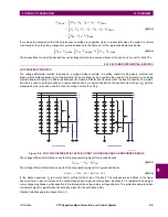
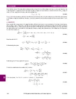
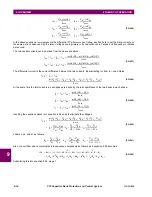
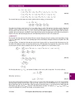
Determination of the two
k
-values using only one equation is possible as the
k
-values are known to be real-valued, so the
complex-valued equation above can be separated into real and imaginary parts, with the same two
k
-values in each. A
solution exists as long as the cross product of the B and C-phase voltages is non-zero; that is, the capacitor bank is in-ser-
vice. However, the assumption made here is that when the auto-set command is executed, the capacitor is in an acceptably
balanced state, wherein the operating signal ought to be zero. Following the auto-set command, the protection will be mea-
suring changes from the state that existed at the time the auto-set command executed.
9.1.5 PHASE CURRENT UNBALANCE (ANSI 60P)
a) OPERATING PRINCIPLE
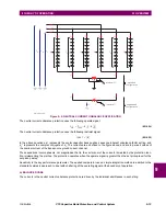
The phase current unbalance function is based on the balance between interconnected and nominally identical phase
strings, and is applicable to both grounded and ungrounded installations. A window CT measuring the vectorial difference
between the two phase currents is required for each phase as shown. While the two phase strings are actually identical, the
measured current is be zero. The failure of an element in either string results in a difference current, which is sensed by the
relay. However, with the two strings slightly mismatched due to manufacturing tolerances, an inherent difference current
may be present. Compensation for this inherent unbalance current is available to increase the sensitivity of the function.
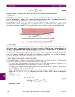
The phase current unbalance function uses the following operate signal.
(EQ 9.43)
In this equation,
k
A
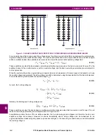
is the capacitor bank leg-A inherent unbalance factor setting. The currents are as defined in the figure
below, and are in per-unit on the nominal current of the differential source. This equation involve phasors, not magnitudes;
that is, the vector sum of the currents is created by the protection function implementing the method.
Figure 9–5: PHASE CURRENT UNBALANCE APPLICATION
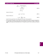
The protection operates when the operate signal is greater than the set pickup level for the set pickup delay. Identical rela-
tions apply to phases B and C.
Sensitivity is the key performance parameter. The applied comparator uses a simple integration method in addition to the
standard hysteresis approach, to deal with chattering of the operating signal at the boundary of operation.
I
OP A
( )
I
DIF A
( )
k
A
I
A
–
=
834747A1.CDR
I
B1
I
A
I
DIF(A)
window CT
grounded or
ungrounded
C
B1
I
A2
C
A2
I
A1
C
A1
I
C2
C
C2
I
C1
C
C1
I
B2
C
B2
I
B
I
C
I
DIF(B)
window CT
I
DIF(C)
window CT
V
X
V
A
Содержание UR Series C70
Страница 2: ......
Страница 10: ...x C70 Capacitor Bank Protection and Control System GE Multilin TABLE OF CONTENTS ...
Страница 30: ...1 20 C70 Capacitor Bank Protection and Control System GE Multilin 1 5 USING THE RELAY 1 GETTING STARTED 1 ...
Страница 124: ...4 30 C70 Capacitor Bank Protection and Control System GE Multilin 4 3 FACEPLATE INTERFACE 4 HUMAN INTERFACES 4 ...
Страница 344: ...5 220 C70 Capacitor Bank Protection and Control System GE Multilin 5 10 TESTING 5 SETTINGS 5 ...
Страница 396: ...8 18 C70 Capacitor Bank Protection and Control System GE Multilin 8 3 ENERVISTA SECURITY MANAGEMENT SYSTEM 8 SECURITY 8 ...
Страница 414: ...9 18 C70 Capacitor Bank Protection and Control System GE Multilin 9 1 OVERVIEW 9 THEORY OF OPERATION 9 ...
Страница 436: ...10 22 C70 Capacitor Bank Protection and Control System GE Multilin 10 4 SETTING EXAMPLE 10 APPLICATION OF SETTINGS 10 ...
Страница 547: ...GE Multilin C70 Capacitor Bank Protection and Control System B 79 APPENDIX B B 4 MEMORY MAPPING B ...
Страница 548: ...B 80 C70 Capacitor Bank Protection and Control System GE Multilin B 4 MEMORY MAPPING APPENDIXB B ...
Страница 586: ...D 10 C70 Capacitor Bank Protection and Control System GE Multilin D 1 OVERVIEW APPENDIXD D ...
Страница 598: ...E 12 C70 Capacitor Bank Protection and Control System GE Multilin E 2 DNP POINT LISTS APPENDIXE E ...

