GE Multilin
C70 Capacitor Bank Protection and Control System
2-3
2 PRODUCT DESCRIPTION
2.1 INTRODUCTION
2
2.1.2 ORDERING
a) OVERVIEW
The C70 is available as a 19-inch rack horizontal mount or reduced-size (¾) vertical unit and consists of the following mod-
ules: power supply, CPU, CT/VT, digital input and output, transducer input and output, and inter-relay communications.
Each of these modules can be supplied in a number of configurations specified at the time of ordering. The information
required to completely specify the relay is provided in the following tables (see chapter 3 for full details of relay modules).
Order codes are subject to change without notice. Refer to the GE Multilin ordering page at
http://www.GEindustrial.com/multilin/order.htm
for the latest details concerning C70 ordering options.
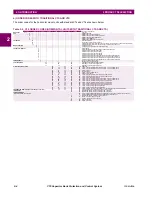
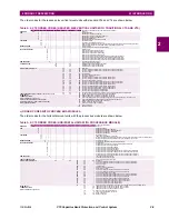
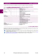
The order code structure is dependent on the mounting option (horizontal or vertical) and the type of CT/VT modules (regu-
lar CT/VT modules or the HardFiber modules). The order code options are described in the following sub-sections.
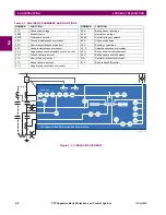
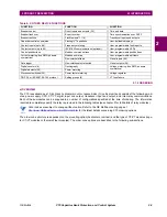
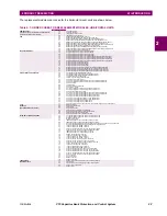
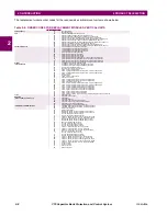
Table 2–2: OTHER DEVICE FUNCTIONS
FUNCTION
FUNCTION
FUNCTION
Breaker control
Direct inputs and outputs (32)
Time and date
Breaker flashover
Event recorder
Time synchronization over SNTP
Breaker restrike
FlexElements™ (16)
Transducer inputs and outputs
Capacitor control supervision
FlexLogic™ equations
User-definable displays
Contact inputs (up to 96)
Frequency metering
User-programmable fault reports
Contact outputs (up to 64)
IEC 61850 communications (optional)
User-programmable LEDs
Control pushbuttons
Modbus communications
User-programmable pushbuttons
Current metering: true RMS, phasors,
symmetrical
Modbus user map
User-programmable self-tests
Non-volatile latches
Virtual inputs (64)
Data logger
Non-volatile selector switch
Virtual outputs (96)
Digital counters (8)
Oscillography
Voltage metering: true RMS, phasors,
symmetrical
Digital elements (48)
Power metering
Disconnect switches (24)
Power factor metering
Voltage regulator
DNP 3.0 or IEC 60870-5-104 protocol
Setting groups (6)
VT fuse failure
NOTE
Содержание UR Series C70
Страница 2: ......
Страница 10: ...x C70 Capacitor Bank Protection and Control System GE Multilin TABLE OF CONTENTS ...
Страница 30: ...1 20 C70 Capacitor Bank Protection and Control System GE Multilin 1 5 USING THE RELAY 1 GETTING STARTED 1 ...
Страница 124: ...4 30 C70 Capacitor Bank Protection and Control System GE Multilin 4 3 FACEPLATE INTERFACE 4 HUMAN INTERFACES 4 ...
Страница 344: ...5 220 C70 Capacitor Bank Protection and Control System GE Multilin 5 10 TESTING 5 SETTINGS 5 ...
Страница 396: ...8 18 C70 Capacitor Bank Protection and Control System GE Multilin 8 3 ENERVISTA SECURITY MANAGEMENT SYSTEM 8 SECURITY 8 ...
Страница 414: ...9 18 C70 Capacitor Bank Protection and Control System GE Multilin 9 1 OVERVIEW 9 THEORY OF OPERATION 9 ...
Страница 436: ...10 22 C70 Capacitor Bank Protection and Control System GE Multilin 10 4 SETTING EXAMPLE 10 APPLICATION OF SETTINGS 10 ...
Страница 547: ...GE Multilin C70 Capacitor Bank Protection and Control System B 79 APPENDIX B B 4 MEMORY MAPPING B ...
Страница 548: ...B 80 C70 Capacitor Bank Protection and Control System GE Multilin B 4 MEMORY MAPPING APPENDIXB B ...
Страница 586: ...D 10 C70 Capacitor Bank Protection and Control System GE Multilin D 1 OVERVIEW APPENDIXD D ...
Страница 598: ...E 12 C70 Capacitor Bank Protection and Control System GE Multilin E 2 DNP POINT LISTS APPENDIXE E ...

