


5-26
C70 Capacitor Bank Protection and Control System
GE Multilin
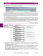
5.2 PRODUCT SETUP
5 SETTINGS
5
–
Set
REMOTE DEVICE 1 ETYPE APPID
to match the ETHERTYPE application ID from the transmitting device. This is
“0” in the example above.
–
Set the
REMOTE DEVICE 1 DATASET
value. This value represents the dataset number in use. Since we are using
configurable GOOSE 1 in this example, program this value as “GOOSEIn 1”.
3.
Configure the data by making the following changes in the
INPUTS/OUTPUTS
ÖØ
REMOTE INPUTS
ÖØ
REMOTE INPUT 1
settings menu:
–
Set
REMOTE IN 1 DEVICE
to “GOOSEOut_1”.
–
Set
REMOTE IN 1 ITEM
to “Dataset Item 2”. This assigns the value of the GGIO3.ST.Ind1.stVal single point status
item to remote input 1.
Remote input 1 can now be used in FlexLogic™ equations or other settings. The C70 must be rebooted (control power
removed and re-applied) before these settings take effect.
The value of remote input 1 (Boolean on or off) in the receiving device will be determined by the GGIO1.ST.Ind1.stVal value
in the sending device. The above settings will be automatically populated by the EnerVista UR Setup software when a com-
plete SCD file is created by third party substation configurator software.
For intercommunication between C70 IEDs, the fixed (DNA/UserSt) dataset can be used. The DNA/UserSt dataset con-
tains the same DNA and UserSt bit pairs that are included in GSSE messages. All GOOSE messages transmitted by the
C70 (DNA/UserSt dataset and configurable datasets) use the IEC 61850 GOOSE messaging services (for example, VLAN
support).
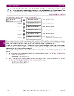
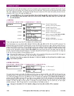
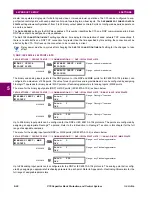
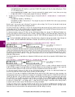
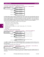
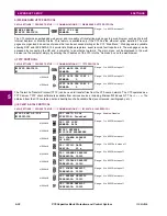
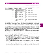
Set the
CONFIG GSE 1 FUNCTION
function to “Disabled” when configuration changes are required. Once changes are
entered, return the
CONFIG GSE 1 FUNCTION
to “Enabled” and restart the unit for changes to take effect.
PATH:...TRANSMISSION
ÖØ
CONFIGURABLE GOOSE 1(8)
ÖØ
CONIFIG GSE 1(64) DATA TIMES
Ö
ITEM 1(64)
To create a configurable GOOSE dataset that contains an IEC 61850 Single Point Status indication and its associated qual-
ity flags, the following dataset items can be selected: “GGIO1.ST.Ind1.stVal” and “GGIO1.ST.Ind1.q”. The C70 will then cre-
ate a dataset containing these two data items. The status value for GGIO1.ST.Ind1.stVal is determined by the FlexLogic™
operand assigned to GGIO1 indication 1. Changes to this operand will result in the transmission of GOOSE messages con-
taining the defined dataset.
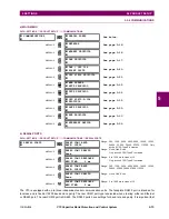
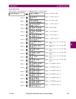
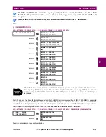
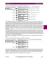
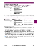
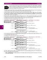
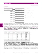
The main reception menu is applicable to configurable GOOSE only and contains the configurable GOOSE dataset items
for reception:
PATH:...RECEPTION
ÖØ
CONFIGURABLE GOOSE 1(8)
ÖØ
CONIFIG GSE 1(64) DATA ITEMS
The configurable GOOSE settings allow the C70 to be configured to receive a number of different datasets within IEC
61850 GOOSE messages. Up to eight different configurable datasets can be configured for reception. This is useful for
intercommunication between C70 IEDs and devices from other manufacturers that support IEC 61850.
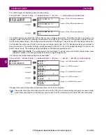
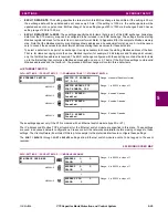
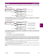
For intercommunication between C70 IEDs, the fixed (DNA/UserSt) dataset can be used. The DNA/UserSt dataset con-
tains the same DNA and UserSt bit pairs that are included in GSSE messages.
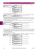
To set up a C70 to receive a configurable GOOSE dataset that contains two IEC 61850 single point status indications, the
following dataset items can be selected (for example, for configurable GOOSE dataset 1): “GGIO3.ST.Ind1.stVal” and
“GGIO3.ST.Ind2.stVal”. The C70 will then create a dataset containing these two data items. The Boolean status values from
these data items can be utilized as remote input FlexLogic™ operands. First, the
REMOTE DEVICE 1(16) DATASET
setting
must be set to contain dataset “GOOSEIn 1” (that is, the first configurable dataset). Then
REMOTE IN 1(16) ITEM
settings
must be set to “Dataset Item 1” and “Dataset Item 2”. These remote input FlexLogic™ operands will then change state in
accordance with the status values of the data items in the configured dataset.
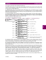
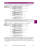
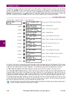
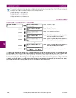
Floating point analog values originating from MMXU logical nodes may be included in GOOSE datasets. Deadband (non-
instantaneous) values can be transmitted. Received values are used to populate the GGIO3.XM.AnIn1 and higher items.
Received values are also available as FlexAnalog parameters (GOOSE analog In1 and up).
CONFIG GSE 1
DATASET ITEMS
ITEM 1:
GGIO1.ST.Ind1.stVal
Range: all valid MMS data item references for
transmitted data
CONFIG GSE 1
DATASET ITEMS
ITEM 1:
GGIO1.ST.Ind1.stVal
Range: all valid MMS data item references for
transmitted data
NOTE
Содержание UR Series C70
Страница 2: ......
Страница 10: ...x C70 Capacitor Bank Protection and Control System GE Multilin TABLE OF CONTENTS ...
Страница 30: ...1 20 C70 Capacitor Bank Protection and Control System GE Multilin 1 5 USING THE RELAY 1 GETTING STARTED 1 ...
Страница 124: ...4 30 C70 Capacitor Bank Protection and Control System GE Multilin 4 3 FACEPLATE INTERFACE 4 HUMAN INTERFACES 4 ...
Страница 344: ...5 220 C70 Capacitor Bank Protection and Control System GE Multilin 5 10 TESTING 5 SETTINGS 5 ...
Страница 396: ...8 18 C70 Capacitor Bank Protection and Control System GE Multilin 8 3 ENERVISTA SECURITY MANAGEMENT SYSTEM 8 SECURITY 8 ...
Страница 414: ...9 18 C70 Capacitor Bank Protection and Control System GE Multilin 9 1 OVERVIEW 9 THEORY OF OPERATION 9 ...
Страница 436: ...10 22 C70 Capacitor Bank Protection and Control System GE Multilin 10 4 SETTING EXAMPLE 10 APPLICATION OF SETTINGS 10 ...
Страница 547: ...GE Multilin C70 Capacitor Bank Protection and Control System B 79 APPENDIX B B 4 MEMORY MAPPING B ...
Страница 548: ...B 80 C70 Capacitor Bank Protection and Control System GE Multilin B 4 MEMORY MAPPING APPENDIXB B ...
Страница 586: ...D 10 C70 Capacitor Bank Protection and Control System GE Multilin D 1 OVERVIEW APPENDIXD D ...
Страница 598: ...E 12 C70 Capacitor Bank Protection and Control System GE Multilin E 2 DNP POINT LISTS APPENDIXE E ...


