


GE Multilin
C70 Capacitor Bank Protection and Control System
5-93
5 SETTINGS
5.5 FLEXLOGIC™
5
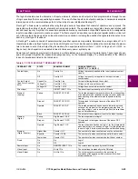
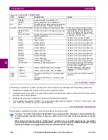
Some operands can be re-named by the user. These are the names of the breakers in the breaker control feature, the ID
(identification) of contact inputs, the ID of virtual inputs, and the ID of virtual outputs. If the user changes the default name
or ID of any of these operands, the assigned name will appear in the relay list of operands. The default names are shown in
the FlexLogic™ operands table above.
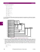
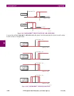
The characteristics of the logic gates are tabulated below, and the operators available in FlexLogic™ are listed in the Flex-
Logic™ operators table.
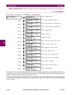
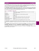
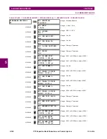
REMOTE DEVICES
REMOTE DEVICE 1 On
↓
REMOTE DEVICE 16 On
Flag is set, logic=1
↓
Flag is set, logic=1
REMOTE DEVICE 1 Off
↓
REMOTE DEVICE 16 Off
Flag is set, logic=1
↓
Flag is set, logic=1
RESETTING
RESET OP
RESET OP (COMMS)
RESET OP (OPERAND)
RESET OP (PUSHBUTTON)
Reset command is operated (set by all three operands below).
Communications source of the reset command.
Operand (assigned in the
INPUTS/OUTPUTS
ÖØ
RESETTING
menu) source
of the reset command.
Reset key (pushbutton) source of the reset command.
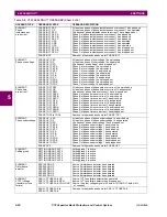
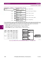
SELF-
DIAGNOSTICS
ANY MAJOR ERROR
ANY MINOR ERROR
ANY SELF-TESTS
BATTERY FAIL
DIRECT DEVICE OFF
DIRECT RING BREAK
EQUIPMENT MISMATCH
ETHERNET SWITCH FAIL
FLEXLOGIC ERR TOKEN
IRIG-B FAILURE
LATCHING OUT ERROR
MAINTENANCE ALERT
PORT 1 OFFLINE
PORT 2 OFFLINE
PORT 3 OFFLINE
PORT 4 OFFLINE
PORT 5 OFFLINE
PORT 6 OFFLINE
PRI ETHERNET FAIL
PROCESS BUS FAILURE
REMOTE DEVICE OFF
RRTD COMM FAIL
SEC ETHERNET FAIL
SNTP FAILURE
SYSTEM EXCEPTION
TEMP MONITOR
UNIT NOT PROGRAMMED
Any of the major self-test errors generated (major error)
Any of the minor self-test errors generated (minor error)
Any self-test errors generated (generic, any error)
See description in
Chapter 7: Commands and targets
See description in
Chapter 7: Commands and targets
See description in
Chapter 7: Commands and targets
See description in
Chapter 7: Commands and targets
See description in
Chapter 7: Commands and targets
See description in
Chapter 7: Commands and targets
See description in
Chapter 7: Commands and targets
See description in
Chapter 7: Commands and targets
See description in
Chapter 7: Commands and targets
See description in
Chapter 7: Commands and targets
See description in
Chapter 7: Commands and targets
See description in
Chapter 7: Commands and targets
See description in
Chapter 7: Commands and targets
See description in
Chapter 7: Commands and targets
See description in
Chapter 7: Commands and targets
See description in
Chapter 7: Commands and targets
See description in
Chapter 7: Commands and targets
See description in
Chapter 7: Commands and targets
See description in
Chapter 7: Commands and targets
See description in
Chapter 7: Commands and targets
See description in
Chapter 7: Commands and targets
See description in
Chapter 7: Commands and targets
See description in
Chapter 7: Commands and targets
See description in
Chapter 7: Commands and targets
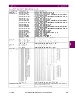
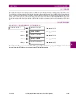
TEMPERATURE
MONITOR
TEMP MONITOR
Asserted while the ambient temperature is greater than the maximum
operating temperature (80°C)
USER-
PROGRAMMABLE
PUSHBUTTONS
PUSHBUTTON 1 ON
PUSHBUTTON 1 OFF
ANY PB ON
Pushbutton number 1 is in the “On” position
Pushbutton number 1 is in the “Off” position
Any of twelve pushbuttons is in the “On” position
PUSHBUTTON 2 to 12
Same set of operands as PUSHBUTTON 1
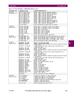
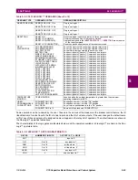
Table 5–9: FLEXLOGIC™ GATE CHARACTERISTICS
GATES
NUMBER OF INPUTS
OUTPUT IS ‘1’ (= ON) IF...
NOT
1
input is ‘0’
OR
2 to 16
any input is ‘1’
AND
2 to 16
all inputs are ‘1’
NOR
2 to 16
all inputs are ‘0’
NAND
2 to 16
any input is ‘0’
XOR
2
only one input is ‘1’
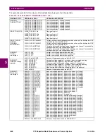
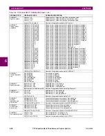
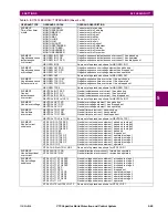
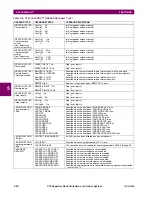
Table 5–8: C70 FLEXLOGIC™ OPERANDS (Sheet 8 of 8)
OPERAND TYPE
OPERAND SYNTAX
OPERAND DESCRIPTION
Содержание UR Series C70
Страница 2: ......
Страница 10: ...x C70 Capacitor Bank Protection and Control System GE Multilin TABLE OF CONTENTS ...
Страница 30: ...1 20 C70 Capacitor Bank Protection and Control System GE Multilin 1 5 USING THE RELAY 1 GETTING STARTED 1 ...
Страница 124: ...4 30 C70 Capacitor Bank Protection and Control System GE Multilin 4 3 FACEPLATE INTERFACE 4 HUMAN INTERFACES 4 ...
Страница 344: ...5 220 C70 Capacitor Bank Protection and Control System GE Multilin 5 10 TESTING 5 SETTINGS 5 ...
Страница 396: ...8 18 C70 Capacitor Bank Protection and Control System GE Multilin 8 3 ENERVISTA SECURITY MANAGEMENT SYSTEM 8 SECURITY 8 ...
Страница 414: ...9 18 C70 Capacitor Bank Protection and Control System GE Multilin 9 1 OVERVIEW 9 THEORY OF OPERATION 9 ...
Страница 436: ...10 22 C70 Capacitor Bank Protection and Control System GE Multilin 10 4 SETTING EXAMPLE 10 APPLICATION OF SETTINGS 10 ...
Страница 547: ...GE Multilin C70 Capacitor Bank Protection and Control System B 79 APPENDIX B B 4 MEMORY MAPPING B ...
Страница 548: ...B 80 C70 Capacitor Bank Protection and Control System GE Multilin B 4 MEMORY MAPPING APPENDIXB B ...
Страница 586: ...D 10 C70 Capacitor Bank Protection and Control System GE Multilin D 1 OVERVIEW APPENDIXD D ...
Страница 598: ...E 12 C70 Capacitor Bank Protection and Control System GE Multilin E 2 DNP POINT LISTS APPENDIXE E ...


