


9-4
C70 Capacitor Bank Protection and Control System
GE Multilin
9.1 OVERVIEW
9 THEORY OF OPERATION
9
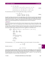
Sensitivity is the key performance parameter. The applied comparator uses a simple integration method in addition to the
standard hysteresis approach, to deal with chattering of the operating signal at the boundary of operation.
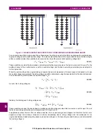
b) BALANCED CASE
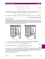
To understand how the voltage differential protection works, consider for simplicity the grounded bank operating equation
below.
(EQ 9.9)
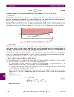
The ungrounded case is similar except that all voltages have
V
X
subtracted. If the initial factory balanced A-leg string has
an initial capacitance of
C
A
, divided into sub-strings with initial capacitances of
C
1
A
and
C
2
A
, and the bank is energized with
system phase-to-ground voltage
V
Spg
, then the string will form a voltage divider and the initial measured voltages are:
(EQ 9.10)
(EQ 9.11)
Substituting these results into equation 8.9, the initial operating signal is:
(EQ 9.12)
The match factor setting
k
A
is chosen as:
(EQ 9.13)
Therefore, as can be seen from the previous two equations, the initial operating signal will be zero.
c) SENSITIVITY
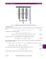
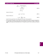
Now consider the consequences of an element failure in the upper sub-string of leg A, making a small capacitance change
in
C
1
A
. The effect on the operating signal can be calculated by taking the derivative of equation 8.12 with respect to
C
A
,
holding
C
2
A
constant. In the general case, the derivative of the absolute value function is messy, but in our case where the
initial value is zero, the derivative of the absolute function is simply the absolute value of the derivative of its argument. The
derivative is thus:
(EQ 9.14)
Substituting equation 8.13, we have:
(EQ 9.15)
This can be written as:
(EQ 9.16)
V
OP A
( )
V
1
A
k
A
V
2
A
–
=
V
1
A
V
Spg
=
V
2
A
V
Spg
C
A
C
2
A
----------
×
=
V
OP A
( )
V
1
A
k
A
V
2
A
–
=
V
Spg
k
A
V
Spg
C
A
C
2
A
----------
×
–
=
V
Spg
1
k
A
C
A
C
2
A
----------
×
–
×
=
k
A
C
2
A
C
A
----------
=
d
dC
A
-----------
V
OP
1
A
(
)
V
Spg
d
dC
A
-----------
1
k
A
C
A
C
2
A
----------
–
⎝
⎠
⎛
⎞
×
=
V
Spg
k
A
C
2
A
----------
–
×
=
V
Spg
k
A
C
2
A
----------
×
=
d
dC
A
-----------
V
OP
1
A
(
)
V
Spg
1
C
A
-------
×
=
or
dV
OP
1
A
(
)
V
Spg
dC
A
C
A
-----------
×
=
V
OP
1
A
(
)
pu
(
)
V
Spg
pu
(
)
C
A
Δ
×
pu
(
)
=
Содержание UR Series C70
Страница 2: ......
Страница 10: ...x C70 Capacitor Bank Protection and Control System GE Multilin TABLE OF CONTENTS ...
Страница 30: ...1 20 C70 Capacitor Bank Protection and Control System GE Multilin 1 5 USING THE RELAY 1 GETTING STARTED 1 ...
Страница 124: ...4 30 C70 Capacitor Bank Protection and Control System GE Multilin 4 3 FACEPLATE INTERFACE 4 HUMAN INTERFACES 4 ...
Страница 344: ...5 220 C70 Capacitor Bank Protection and Control System GE Multilin 5 10 TESTING 5 SETTINGS 5 ...
Страница 396: ...8 18 C70 Capacitor Bank Protection and Control System GE Multilin 8 3 ENERVISTA SECURITY MANAGEMENT SYSTEM 8 SECURITY 8 ...
Страница 414: ...9 18 C70 Capacitor Bank Protection and Control System GE Multilin 9 1 OVERVIEW 9 THEORY OF OPERATION 9 ...
Страница 436: ...10 22 C70 Capacitor Bank Protection and Control System GE Multilin 10 4 SETTING EXAMPLE 10 APPLICATION OF SETTINGS 10 ...
Страница 547: ...GE Multilin C70 Capacitor Bank Protection and Control System B 79 APPENDIX B B 4 MEMORY MAPPING B ...
Страница 548: ...B 80 C70 Capacitor Bank Protection and Control System GE Multilin B 4 MEMORY MAPPING APPENDIXB B ...
Страница 586: ...D 10 C70 Capacitor Bank Protection and Control System GE Multilin D 1 OVERVIEW APPENDIXD D ...
Страница 598: ...E 12 C70 Capacitor Bank Protection and Control System GE Multilin E 2 DNP POINT LISTS APPENDIXE E ...


