GE Multilin
C70 Capacitor Bank Protection and Control System
10-5
10 APPLICATION OF SETTINGS
10.3 PROTECTION METHODS FOR CAPACITOR BANKS
10
10.3PROTECTION METHODS FOR CAPACITOR BANKS
10.3.1 DESCRIPTION
The protection of shunt capacitor banks involves both bank and system protection schemes.
Bank protection schemes are provided for faults within the capacitor bank itself. Bank protection may include items such as
a means to disconnect a faulted capacitor unit or capacitor elements, a means to initiate a shutdown of the bank in case of
faults that may lead to a catastrophic failure, and alarms to indicate unbalance within the bank.
System protection schemes are provided to protect the capacitor bank from stresses that may be caused by the system
and to protect the substation and system from stresses that may be caused by the operation of the capacitor bank. System
protection may include items such as a means to limit overvoltage and excessive transient overcurrents, and to disconnect
the bank in the event of a major fault within the capacitor installation. System protection may also include alarms and meth-
ods to disconnect the entire shunt capacitor bank to prevent further damage to the capacitors due to abnormal system con-
ditions.
In externally fused capacitor banks, several capacitor element breakdowns may occur before the fuse removes the entire
unit. The external fuse will operate when a capacitor unit becomes (essentially) short circuited, isolating the faulted unit.
Unbalance protection removes the bank from service when the resulting overvoltage becomes excessive on the remaining
healthy capacitor units.
Internally fused capacitors have individual capacitor elements within a capacitor unit that are disconnected when an ele-
ment breakdown occurs. The risk of successive faults is minimized because the fuse will isolate the faulty element within a
few cycles. Unbalance protection removes the bank from service when the resulting unbalanced voltage becomes exces-
sive on the remaining healthy capacitor elements or units.
For fuseless or unfused capacitor banks, a failed element is short-circuited by the weld that naturally occurs at the point of
failure. Unbalance protection removes the bank from service when the resulting voltage becomes excessive on the remain-
ing healthy capacitor elements or units.
10.3.2 CAPACITOR UNBALANCE PROTECTION
a) CONNECTIONS
Unbalance protection utilizes the unbalance that occurs in a normally balanced capacitor bank to detect an abnormality and
initiate appropriate action. The most important function is to promptly remove the bank from service for any fault that may
result in further damage. Capacitor unbalance protection is provided in many different ways, depending on the capacitor
bank arrangement.
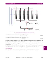
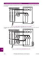
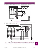
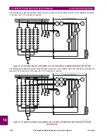
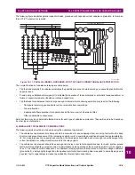
The variety of unbalance protection schemes that may be applied with C70 for internally fused, externally fused, fuseless,
or unfused shunt capacitor banks is indicated in
Theory of operation
chapter and is illustrated on the figures below.
Содержание UR Series C70
Страница 2: ......
Страница 10: ...x C70 Capacitor Bank Protection and Control System GE Multilin TABLE OF CONTENTS ...
Страница 30: ...1 20 C70 Capacitor Bank Protection and Control System GE Multilin 1 5 USING THE RELAY 1 GETTING STARTED 1 ...
Страница 124: ...4 30 C70 Capacitor Bank Protection and Control System GE Multilin 4 3 FACEPLATE INTERFACE 4 HUMAN INTERFACES 4 ...
Страница 344: ...5 220 C70 Capacitor Bank Protection and Control System GE Multilin 5 10 TESTING 5 SETTINGS 5 ...
Страница 396: ...8 18 C70 Capacitor Bank Protection and Control System GE Multilin 8 3 ENERVISTA SECURITY MANAGEMENT SYSTEM 8 SECURITY 8 ...
Страница 414: ...9 18 C70 Capacitor Bank Protection and Control System GE Multilin 9 1 OVERVIEW 9 THEORY OF OPERATION 9 ...
Страница 436: ...10 22 C70 Capacitor Bank Protection and Control System GE Multilin 10 4 SETTING EXAMPLE 10 APPLICATION OF SETTINGS 10 ...
Страница 547: ...GE Multilin C70 Capacitor Bank Protection and Control System B 79 APPENDIX B B 4 MEMORY MAPPING B ...
Страница 548: ...B 80 C70 Capacitor Bank Protection and Control System GE Multilin B 4 MEMORY MAPPING APPENDIXB B ...
Страница 586: ...D 10 C70 Capacitor Bank Protection and Control System GE Multilin D 1 OVERVIEW APPENDIXD D ...
Страница 598: ...E 12 C70 Capacitor Bank Protection and Control System GE Multilin E 2 DNP POINT LISTS APPENDIXE E ...

