5-174
C70 Capacitor Bank Protection and Control System
GE Multilin
5.7 CONTROL ELEMENTS
5 SETTINGS
5
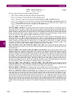
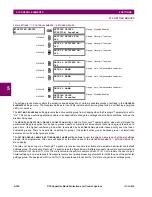
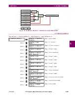
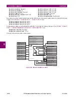
The capacitor control element gathers on/off commands from various sources and executes them, while maintaining
remote/local and auto/manual control rights. Local control refers to control from the front panel of the relay. Remote control
refers to control via communications from outside of the relay, an on-site interface, and/or from an off-site control center.
However, there is flexibility to support other configurations.
This element provides a user-programmable time delay that inhibits closing after the bank has been switched out of service
until the bank has had time to discharge any trapped charge. If the capacitor were to be closed with trapped charge of
opposite polarity from the system voltage at that instant, larger than normal transients would occur. A FlexAnalog value is
available to inform the time remaining before the next permissible close operation.
Seal-in is provided to stretch short input commands to lengths suitable for breaker control. An interlock prevents simultane-
ous trip and close output, which could result in breaker pumping. To prevent a continuous close input from causing reclos-
ing of the breaker following a trip command, the interlock is sealed-in for the duration of any close input.
A provision is provided to force the auto/manual mode to manual on protection operation. This is to prevent the capacitor
automatic switching scheme from attempting to close a faulted capacitor. A setting is used to control the automatic switcho-
ver to manual upon the protection trip.
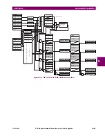
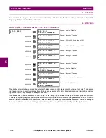
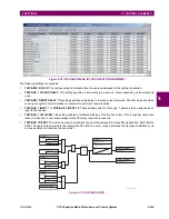
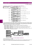
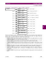
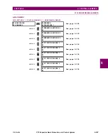
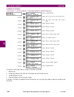
The following settings are available for each capacitor control element.
•
CAP 1 CTRL FUNCTION
: This setting is used to enable the element. When disabled, the remote/local latch is forced
to local, the auto/manual latch is forced to manual, the trip and close command outputs are forced off, and their seal-in
latches and timers are reset.
•
CAP 1 SET REMOTE 1(2)
: Sets one or two FlexLogic™ operands to select the remote mode. It is expected that one of
these settings is programmed to a pushbutton “on” operand. This allows a local operator to hand over control to remote
operators. Where appropriate, the other one of these settings may be set to a virtual input. This allows remote opera-
tors to grant themselves control rights.
•
CAP 1 SET LOCAL 1(2)
: Similar to previous setting, but selects local mode.
•
CAP 1 RMT CTRL EN
: Selects a FlexLogic™ operand to enables remote auto/manual and open/close control. It is
expected that this will be set to
CAP 1 IN REMOTE
to obtain the baseline functionality, but variations via FlexLogic™ are
possible. For example, should it be required that remote control is always available, this setting may be set to “On”.
•
CAP 1 LCL CTRL EN
: Similar to previous setting, but enables local controls. Expected to be set to
CAP 1 IN LOCAL
.
•
CAP 1 RMT SET AUTO
: Selects a FlexLogic™ operand that selects auto mode when remote control is enabled. It is
expected that this will be set to a virtual input to enables HMI/SCADA access via one of the supported protocols.
•
CAP 1 LCL SET AUTO
: Similar to previous setting, but expected to be set to a pushbutton “on” operand.
•
CAP 1 RMT SET MAN
: Similar to the
CAP RMT SET AUTO
setting, but selects manual mode.
•
CAP 1 LCL SET MAN
: Similar to the
CAP LCL SET AUTO
setting, but selects manual mode.
•
CAP 1 TRIP 1(6)
: Selects up to six FlexLogic™ operands to activate the
CAP 1 BKR TRIP
operand, no matter what con-
trol modes prevail. Expected to be set to the appropriate protection element operate operand.
•
CAP 1 SWITCH TO MANUAL ON TRIP
: This setting allows controlling the auto/manual mode when issuing a trip
command. If set to “Yes” the element will switch to manual mode upon tripping the bank from protection.
•
CAP 1 AUTO CTRL EN
: Selects a FlexLogic™ operand to enable automatic open/close control. It is expected that this
will be set to
CAP 1 IN AUTO
to obtain the baseline functionality, but variations are possible.
•
CAP 1 MAN CTRL EN
: Similar to previous setting, but enables manual controls. Expected to be set to
CAP 1 IN MAN
.
•
CAP 1 REMOTE OPEN
: Selects a FlexLogic™ operand to activate the
CAP 1 BKR TRIP
operand when both remote
and manual control are enabled. It is expected that this will be set to a virtual input, and that the contact output wired to
the capacitor breaker trip coil is set to
CAP 1 BKR TRIP
.
•
CAP 1 LOCAL OPEN
: Similar to previous setting, but requires both local and manual control to be enabled. Expected
to be set to a pushbutton “on” operand.
•
CAP 1 AUTO OPEN
: Similar to previous setting, but requires automatic control to be enabled. Expected to be set to
the open command of the voltage regulator either built-in or customer via FlexLogic™.
•
CAP 1 BKR OPEN 52b
: Selects a FlexLogic™ operand that cancels the trip seal-in. Expected to be set to the contact
input to which a contact is wired that is closed when the capacitor breaker is open. When both 52a and 52b contacts
Содержание UR Series C70
Страница 2: ......
Страница 10: ...x C70 Capacitor Bank Protection and Control System GE Multilin TABLE OF CONTENTS ...
Страница 30: ...1 20 C70 Capacitor Bank Protection and Control System GE Multilin 1 5 USING THE RELAY 1 GETTING STARTED 1 ...
Страница 124: ...4 30 C70 Capacitor Bank Protection and Control System GE Multilin 4 3 FACEPLATE INTERFACE 4 HUMAN INTERFACES 4 ...
Страница 344: ...5 220 C70 Capacitor Bank Protection and Control System GE Multilin 5 10 TESTING 5 SETTINGS 5 ...
Страница 396: ...8 18 C70 Capacitor Bank Protection and Control System GE Multilin 8 3 ENERVISTA SECURITY MANAGEMENT SYSTEM 8 SECURITY 8 ...
Страница 414: ...9 18 C70 Capacitor Bank Protection and Control System GE Multilin 9 1 OVERVIEW 9 THEORY OF OPERATION 9 ...
Страница 436: ...10 22 C70 Capacitor Bank Protection and Control System GE Multilin 10 4 SETTING EXAMPLE 10 APPLICATION OF SETTINGS 10 ...
Страница 547: ...GE Multilin C70 Capacitor Bank Protection and Control System B 79 APPENDIX B B 4 MEMORY MAPPING B ...
Страница 548: ...B 80 C70 Capacitor Bank Protection and Control System GE Multilin B 4 MEMORY MAPPING APPENDIXB B ...
Страница 586: ...D 10 C70 Capacitor Bank Protection and Control System GE Multilin D 1 OVERVIEW APPENDIXD D ...
Страница 598: ...E 12 C70 Capacitor Bank Protection and Control System GE Multilin E 2 DNP POINT LISTS APPENDIXE E ...

