5-178
C70 Capacitor Bank Protection and Control System
GE Multilin
5.7 CONTROL ELEMENTS
5 SETTINGS
5
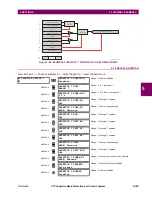
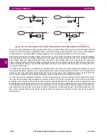
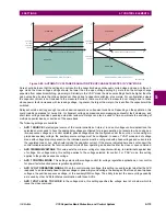
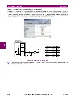
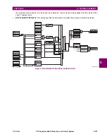
Figure 5–88: APPLICATIONS OF THE CAPACITOR AUTOMATIC VOLTAGE REGULATOR FUNCTION
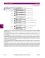
Up to three identical automatic voltage regulator elements are provided, allowing the relay to be used with capacitor banks
divided into sections for finer compensation steps, to provide switching speed dependant on the extent of the voltage or
power deviation, or to provide different settings depending on a user-programmable factor such as time of day.
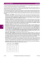
Each element can be set to operate in either “Voltage” mode or “VAR” mode. The voltage mode can be used with relatively
short time delay settings as a system stability aid, or with longer time delay settings to assist in the regulation of steady
state voltage. When the voltage decreases to the volts level to close setting, after the set close delay the capacitor is
closed, raising the voltage. When the voltage increases to the level to open setting, after the set open delay the capacitor is
opened, lowering the voltage. The load drop compensation feature can be used to effectively sense the voltage at a loca-
tion remote from the relay.
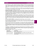
The “VAR” mode can be used to regulate the var and power factor of a load to reduce transmission and distribution costs. If
the capacitor deployment objective is to minimize system power losses, set the power factor limit to 1.000 to disable it and
set the var open and close levels symmetrically about zero reactive power, with a difference between levels equal to the
reactive power produced by the capacitor plus margin. Larger margins result in less frequent switching.
If on the other hand the deployment objective is solely to minimize power factor rate charges, set the power factor limit to
the value at which power factor penalties are incurred, typically 0.9. Set the var close level to the vars that would flow
should the power factor be at the limit when at the minimum expected kW demand. The open command characteristics can
be selected to suit whether the preference is to minimize the amount of time the capacitor is online or to minimize the num-
ber of capacitor close operations. For the former preference, set the var open mode to “Minimize Uptime” and set the var
open level below the close level by an amount equal to the capacitor var rating plus margin. For the latter preference, set
the var open mode to “Minimize No. of Ops” (minimize number of operations) and set the var open level to the negative of
the close level.
System
AVR
Load
a) System voltage regulation
System
AVR
Load
b) Load voltage regulation
feeder
impedance
System
AVR
Load
c) Load power factor regulation
System
AVR
Load
d) Load power factor regulation, alternate configuration
834731A1.CDR
Содержание UR Series C70
Страница 2: ......
Страница 10: ...x C70 Capacitor Bank Protection and Control System GE Multilin TABLE OF CONTENTS ...
Страница 30: ...1 20 C70 Capacitor Bank Protection and Control System GE Multilin 1 5 USING THE RELAY 1 GETTING STARTED 1 ...
Страница 124: ...4 30 C70 Capacitor Bank Protection and Control System GE Multilin 4 3 FACEPLATE INTERFACE 4 HUMAN INTERFACES 4 ...
Страница 344: ...5 220 C70 Capacitor Bank Protection and Control System GE Multilin 5 10 TESTING 5 SETTINGS 5 ...
Страница 396: ...8 18 C70 Capacitor Bank Protection and Control System GE Multilin 8 3 ENERVISTA SECURITY MANAGEMENT SYSTEM 8 SECURITY 8 ...
Страница 414: ...9 18 C70 Capacitor Bank Protection and Control System GE Multilin 9 1 OVERVIEW 9 THEORY OF OPERATION 9 ...
Страница 436: ...10 22 C70 Capacitor Bank Protection and Control System GE Multilin 10 4 SETTING EXAMPLE 10 APPLICATION OF SETTINGS 10 ...
Страница 547: ...GE Multilin C70 Capacitor Bank Protection and Control System B 79 APPENDIX B B 4 MEMORY MAPPING B ...
Страница 548: ...B 80 C70 Capacitor Bank Protection and Control System GE Multilin B 4 MEMORY MAPPING APPENDIXB B ...
Страница 586: ...D 10 C70 Capacitor Bank Protection and Control System GE Multilin D 1 OVERVIEW APPENDIXD D ...
Страница 598: ...E 12 C70 Capacitor Bank Protection and Control System GE Multilin E 2 DNP POINT LISTS APPENDIXE E ...

