


GE Multilin
C70 Capacitor Bank Protection and Control System
9-3
9 THEORY OF OPERATION
9.1 OVERVIEW
9
(EQ 9.5)
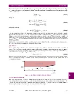
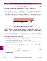
If we make the assumption that the zero-sequence voltage is negligible, which is reasonable when the system is normal
(non-faulted), then the string voltages for grounded banks are the same as for the ungrounded balanced banks:
(EQ 9.6)
These quantities are what the bank phase overvoltage protection measures whenever the bus source is set for delta VTs.
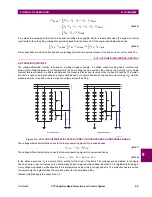
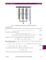
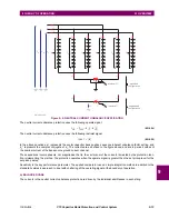
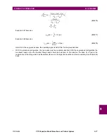
9.1.3 VOLTAGE DIFFERENTIAL (ANSI 87V)
a) OPERATING PRINCIPLE
The voltage differential function is based on a voltage divider principle - a healthy capacitor string has a constant and
known match factor between its full tap (typically the bus voltage) and an auxiliary tap used by the protection. Any single
element failure will result in a difference between the measured factor and its value when the bank is healthy. The protec-
tion can be used on both grounded and ungrounded banks. For ungrounded banks, the neutral point voltage (
V
X
) must be
measured by the relay, and used to derive the voltage across the string.
Figure 9–2: VOLTAGE DIFFERENTIAL APPLICATION TO GROUNDED AND UNGROUNDED BANKS
The voltage differential protection uses the following operating signal for grounded banks.
(EQ 9.7)
The voltage differential protection uses the following operating signal for ungrounded banks.
(EQ 9.8)
In the above equations,
k
A
is a match factor setting for the A-leg of the bank. The voltages are as defined in the figure
above, and are in per-unit values on the nominal bus phase-to-ground voltage base. Equation 8.7 is implemented using pri-
mary voltage magnitudes, while equation 8.8 is implemented using primary voltage phasors. The protection operates when
the operate signal is greater than the set pickup level for the set pickup delay.
Identical relations apply to phases B and C.
V
A
RMS
1
3
---
3
V
A
V
B
V
B
–
(
)
V
C
V
C
–
(
)
+
+
RMS
=
1
3
---
V
A
V
B
–
V
C
–
V
A
V
A
V
B
V
C
+
+
(
)
+
+
RMS
=
1
3
---
V
AB
V
CA
–
3
V
0
+
RMS
=
1
3
---
V
AB
V
CA
–
RMS
,
1
3
---
V
BC
V
AB
–
RMS
, or
1
3
---
V
CA
V
BC
–
RMS
834750A1.CDR
Grounded bank
Ungrounded bank
V
2A
V
1A
A
B
C
C
1A
C
2A
C
A
V
X
V
2A
V
1A
A
B
C
C
1A
C
2A
C
A
V
OP A
( )
V
1
A
k
A
V
2
A
–
=
V
OP A
( )
V
1
A
V
X
–
(
)
k
A
V
2
A
V
X
–
(
)
–
=
Содержание UR Series C70
Страница 2: ......
Страница 10: ...x C70 Capacitor Bank Protection and Control System GE Multilin TABLE OF CONTENTS ...
Страница 30: ...1 20 C70 Capacitor Bank Protection and Control System GE Multilin 1 5 USING THE RELAY 1 GETTING STARTED 1 ...
Страница 124: ...4 30 C70 Capacitor Bank Protection and Control System GE Multilin 4 3 FACEPLATE INTERFACE 4 HUMAN INTERFACES 4 ...
Страница 344: ...5 220 C70 Capacitor Bank Protection and Control System GE Multilin 5 10 TESTING 5 SETTINGS 5 ...
Страница 396: ...8 18 C70 Capacitor Bank Protection and Control System GE Multilin 8 3 ENERVISTA SECURITY MANAGEMENT SYSTEM 8 SECURITY 8 ...
Страница 414: ...9 18 C70 Capacitor Bank Protection and Control System GE Multilin 9 1 OVERVIEW 9 THEORY OF OPERATION 9 ...
Страница 436: ...10 22 C70 Capacitor Bank Protection and Control System GE Multilin 10 4 SETTING EXAMPLE 10 APPLICATION OF SETTINGS 10 ...
Страница 547: ...GE Multilin C70 Capacitor Bank Protection and Control System B 79 APPENDIX B B 4 MEMORY MAPPING B ...
Страница 548: ...B 80 C70 Capacitor Bank Protection and Control System GE Multilin B 4 MEMORY MAPPING APPENDIXB B ...
Страница 586: ...D 10 C70 Capacitor Bank Protection and Control System GE Multilin D 1 OVERVIEW APPENDIXD D ...
Страница 598: ...E 12 C70 Capacitor Bank Protection and Control System GE Multilin E 2 DNP POINT LISTS APPENDIXE E ...


