GE Multilin
C70 Capacitor Bank Protection and Control System
5-155
5 SETTINGS
5.6 GROUPED ELEMENTS
5
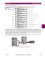
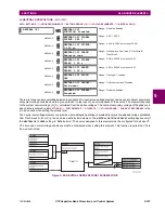
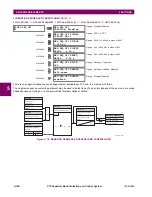
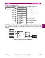
When fed from wye-connected VTs, thus function responds to phase-to-ground voltages. When fed from delta-connected
VTs, this function responds to the vector difference between the phase-to-phase voltages.
The function responds to true RMS voltages to account for effects of harmonics (harmonics impacting losses in the capaci-
tor, harmonics increasing peak values in the voltages compared with the filtered fundamental frequency magnitudes).
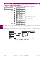
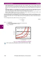
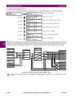
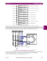
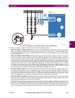
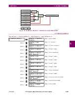
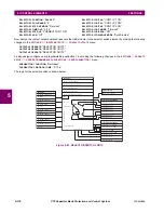
Figure 5–74: BANK OVERVOLTAGE BASIC CONNECTIONS
For more information refer to the
Theory of Operation
and
Application of Settings
chapters. The following settings are avail-
able for each bank phase overvoltage element.
•
BANK OV 1 BUS SOURCE
: This setting indicates the signal source that signifies the bus voltage of the capacitor
bank. The function uses this source as reference for per-unit (pu) settings of the pickup thresholds. The VT ratio and
secondary nominal voltage are set under the
SETTINGS
ÖØ
SYSTEM SETUP
Ö
AC INPUTS
ÖØ
VOLTAGE BANK
menu.
•
BANK OV 1 NTRL SOURCE
: This setting indicates the signal source that signifies the neutral-point voltage of the
bank. The auxiliary voltage channel of this source is used, and must be labelled “Vn” under the VT setup menu. The
neutral point voltage is used only when the function is applied to an ungrounded bank, to derive the true voltage drop
across the capacitors. The VT ratio and secondary nominal voltage are set under the
SETTINGS
ÖØ
SYSTEM SETUP
Ö
AC INPUTS
ÖØ
VOLTAGE BANK
menu.
•
BANK OV 1 BANK GROUND
: This setting indicates if the protected bank is grounded, ungrounded with the neutral
point voltage measured, and ungrounded without the neutral point voltage. The relay automatically compensates for
potentially different VT ratios and secondary voltages of the bus and neutral point voltages. The following table
explains the operating signals of the function based on the input signals available to the relay.
VT
CONNECTION
BANK CONFIGURATION
GROUNDED
UNGROUNDED
UNGROUNDED W/O VN
Wye
Vop_A = VA
Vop_B = VB
Vop_C = VC
Vop_A = VA – VX
Vop_B = VB – VX
Vop_C = VC – VX
Vop_A = (VCA – VAB) / 3
Vop_B = (VAB – VBC) / 3
Vop_C = (VBC – VCA) / 3
Delta
Vop_A = (VCA – VAB) / 3
Vop_B = (VAB – VBC) / 3
Vop_C = (VBC – VCA) / 3
Alternative: delta
connected VTs
C70 CAPACITOR BANK RELAY
59B
BUS
SRC
NTRL
SRC
Phase
VT Bank
Aux VT
For ungrounded
banks only
834734A1.DWG
Содержание UR Series C70
Страница 2: ......
Страница 10: ...x C70 Capacitor Bank Protection and Control System GE Multilin TABLE OF CONTENTS ...
Страница 30: ...1 20 C70 Capacitor Bank Protection and Control System GE Multilin 1 5 USING THE RELAY 1 GETTING STARTED 1 ...
Страница 124: ...4 30 C70 Capacitor Bank Protection and Control System GE Multilin 4 3 FACEPLATE INTERFACE 4 HUMAN INTERFACES 4 ...
Страница 344: ...5 220 C70 Capacitor Bank Protection and Control System GE Multilin 5 10 TESTING 5 SETTINGS 5 ...
Страница 396: ...8 18 C70 Capacitor Bank Protection and Control System GE Multilin 8 3 ENERVISTA SECURITY MANAGEMENT SYSTEM 8 SECURITY 8 ...
Страница 414: ...9 18 C70 Capacitor Bank Protection and Control System GE Multilin 9 1 OVERVIEW 9 THEORY OF OPERATION 9 ...
Страница 436: ...10 22 C70 Capacitor Bank Protection and Control System GE Multilin 10 4 SETTING EXAMPLE 10 APPLICATION OF SETTINGS 10 ...
Страница 547: ...GE Multilin C70 Capacitor Bank Protection and Control System B 79 APPENDIX B B 4 MEMORY MAPPING B ...
Страница 548: ...B 80 C70 Capacitor Bank Protection and Control System GE Multilin B 4 MEMORY MAPPING APPENDIXB B ...
Страница 586: ...D 10 C70 Capacitor Bank Protection and Control System GE Multilin D 1 OVERVIEW APPENDIXD D ...
Страница 598: ...E 12 C70 Capacitor Bank Protection and Control System GE Multilin E 2 DNP POINT LISTS APPENDIXE E ...

