


E-10
C70 Capacitor Bank Protection and Control System
GE Multilin
E.2 DNP POINT LISTS
APPENDIX E
E
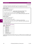
E.2.3 COUNTERS
The following table lists both Binary Counters (Object 20) and Frozen Counters (Object 21). When a freeze function is per-
formed on a Binary Counter point, the frozen value is available in the corresponding Frozen Counter point.
A counter freeze command has no meaning for counters 8 and 9. C70 Digital Counter values are represented as 32-bit
integers. The DNP 3.0 protocol defines counters to be unsigned integers. Care should be taken when interpreting negative
counter values.
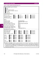
BINARY COUNTERS
Static (Steady-State) Object Number:
20
Change Event Object Number:
22
Request Function Codes supported:
1 (read), 7 (freeze), 8 (freeze noack), 9 (freeze and clear),
10 (freeze and clear, noack), 22 (assign class)
Static Variation reported when variation 0 requested:
1 (32-Bit Binary Counter with Flag)
Change Event Variation reported when variation 0 requested:
1 (32-Bit Counter Change Event without time)
Change Event Buffer Size:
10
Default Class for all points:
3
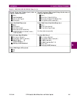
FROZEN COUNTERS
Static (Steady-State) Object Number:
21
Change Event Object Number:
23
Request Function Codes supported:
1 (read)
Static Variation reported when variation 0 requested:
1 (32-Bit Frozen Counter with Flag)
Change Event Variation reported when variation 0 requested:
1 (32-Bit Frozen Counter Event without time)
Change Event Buffer Size:
10
Default Class for all points:
3
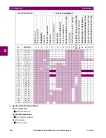
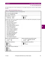
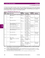
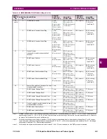
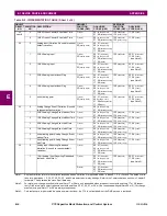
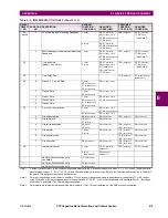
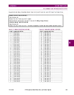
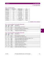
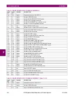
Table E–4: BINARY AND FROZEN COUNTERS
POINT
INDEX
NAME/DESCRIPTION
0
Digital Counter 1
1
Digital Counter 2
2
Digital Counter 3
3
Digital Counter 4
4
Digital Counter 5
5
Digital Counter 6
6
Digital Counter 7
7
Digital Counter 8
8
Oscillography Trigger Count
9
Events Since Last Clear
Содержание UR Series C70
Страница 2: ......
Страница 10: ...x C70 Capacitor Bank Protection and Control System GE Multilin TABLE OF CONTENTS ...
Страница 30: ...1 20 C70 Capacitor Bank Protection and Control System GE Multilin 1 5 USING THE RELAY 1 GETTING STARTED 1 ...
Страница 124: ...4 30 C70 Capacitor Bank Protection and Control System GE Multilin 4 3 FACEPLATE INTERFACE 4 HUMAN INTERFACES 4 ...
Страница 344: ...5 220 C70 Capacitor Bank Protection and Control System GE Multilin 5 10 TESTING 5 SETTINGS 5 ...
Страница 396: ...8 18 C70 Capacitor Bank Protection and Control System GE Multilin 8 3 ENERVISTA SECURITY MANAGEMENT SYSTEM 8 SECURITY 8 ...
Страница 414: ...9 18 C70 Capacitor Bank Protection and Control System GE Multilin 9 1 OVERVIEW 9 THEORY OF OPERATION 9 ...
Страница 436: ...10 22 C70 Capacitor Bank Protection and Control System GE Multilin 10 4 SETTING EXAMPLE 10 APPLICATION OF SETTINGS 10 ...
Страница 547: ...GE Multilin C70 Capacitor Bank Protection and Control System B 79 APPENDIX B B 4 MEMORY MAPPING B ...
Страница 548: ...B 80 C70 Capacitor Bank Protection and Control System GE Multilin B 4 MEMORY MAPPING APPENDIXB B ...
Страница 586: ...D 10 C70 Capacitor Bank Protection and Control System GE Multilin D 1 OVERVIEW APPENDIXD D ...
Страница 598: ...E 12 C70 Capacitor Bank Protection and Control System GE Multilin E 2 DNP POINT LISTS APPENDIXE E ...


