GE Multilin
C70 Capacitor Bank Protection and Control System
5-203
5 SETTINGS
5.8 INPUTS/OUTPUTS
5
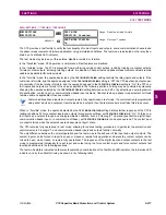
c) REMOTE DEVICES: ID OF DEVICE FOR RECEIVING GSSE MESSAGES
PATH: SETTINGS
ÖØ
INPUTS/OUTPUTS
ÖØ
REMOTE DEVICES
Ö
REMOTE DEVICE 1(16)
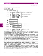
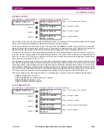
Remote devices are available for setting purposes. A receiving relay must be programmed to capture messages from only
those originating remote devices of interest. This setting is used to select specific remote devices by entering (bottom row)
the exact identification (ID) assigned to those devices.
The
REMOTE DEVICE 1 ETYPE APPID
setting is only used with GOOSE messages; they are not applicable to GSSE mes-
sages. This setting identifies the Ethernet application identification in the GOOSE message. It should match the corre-
sponding settings on the sending device.
The
REMOTE DEVICE 1 DATASET
setting provides for the choice of the C70 fixed (DNA/UserSt) dataset (that is, containing
DNA and UserSt bit pairs), or one of the configurable datasets.
Note that the dataset for the received data items must be made up of existing items in an existing logical node. For this rea-
son, logical node GGIO3 is instantiated to hold the incoming data items. GGIO3 is not necessary to make use of the
received data. The remote input data item mapping takes care of the mapping of the inputs to remote input FlexLogic™
operands. However, GGIO3 data can be read by IEC 61850 clients.
5.8.6 REMOTE INPUTS
PATH: SETTINGS
ÖØ
INPUTS/OUTPUTS
ÖØ
REMOTE INPUTS
Ö
REMOTE INPUT 1(32)
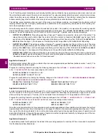
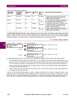
Remote Inputs that create FlexLogic™ operands at the receiving relay are extracted from GSSE/GOOSE messages origi-
nating in remote devices. Each remote input can be selected from a list consisting of 64 selections: DNA-1 through DNA-32
and UserSt-1 through UserSt-32. The function of DNA inputs is defined in the IEC 61850 specification and is presented in
the IEC 61850 DNA Assignments table in the
Remote outputs
section. The function of UserSt inputs is defined by the user
selection of the FlexLogic™ operand whose state is represented in the GSSE/GOOSE message. A user must program a
DNA point from the appropriate FlexLogic™ operand.
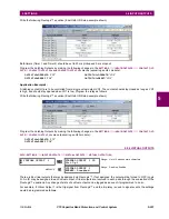
Remote input 1 must be programmed to replicate the logic state of a specific signal from a specific remote device for local
use. This programming is performed via the three settings shown above.
The
REMOTE INPUT 1 ID
setting allows the user to assign descriptive text to the remote input. The
REMOTE IN 1 DEVICE
setting
selects the number (1 to 16) of the remote device which originates the required signal, as previously assigned to the remote
device via the setting
REMOTE DEVICE 1(16) ID
(see the
Remote devices
section). The
REMOTE IN 1 ITEM
setting selects the
specific bits of the GSSE/GOOSE message required.
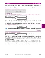
The
REMOTE IN 1 DEFAULT STATE
setting selects the logic state for this point if the local relay has just completed startup or
the remote device sending the point is declared to be non-communicating. The following choices are available:
REMOTE DEVICE 1
REMOTE DEVICE 1 ID:
Remote Device 1
Range: up to 20 alphanumeric characters
MESSAGE
REMOTE DEVICE 1
ETYPE APPID: 0
Range: 0 to 16383 in steps of 1
MESSAGE
REMOTE DEVICE 1
DATASET: Fixed
Range: Fixed, GOOSE 1 through GOOSE 8
REMOTE INPUT 1
REMOTE INPUT 1 ID:
Remote Ip 1
Range: up to 12 alphanumeric characters
MESSAGE
REMOTE IN 1 DEVICE:
Remote Device 1
Range: 1 to 16 inclusive
MESSAGE
REMOTE IN 1 ITEM:
None
Range: None, DNA-1 to DNA-32, UserSt-1 to UserSt-32,
Config Item 1 to Config Item 64
MESSAGE
REMOTE IN 1 DEFAULT
STATE: Off
Range: On, Off, Latest/On, Latest/Off
MESSAGE
REMOTE IN 1
EVENTS: Disabled
Range: Disabled, Enabled
Содержание UR Series C70
Страница 2: ......
Страница 10: ...x C70 Capacitor Bank Protection and Control System GE Multilin TABLE OF CONTENTS ...
Страница 30: ...1 20 C70 Capacitor Bank Protection and Control System GE Multilin 1 5 USING THE RELAY 1 GETTING STARTED 1 ...
Страница 124: ...4 30 C70 Capacitor Bank Protection and Control System GE Multilin 4 3 FACEPLATE INTERFACE 4 HUMAN INTERFACES 4 ...
Страница 344: ...5 220 C70 Capacitor Bank Protection and Control System GE Multilin 5 10 TESTING 5 SETTINGS 5 ...
Страница 396: ...8 18 C70 Capacitor Bank Protection and Control System GE Multilin 8 3 ENERVISTA SECURITY MANAGEMENT SYSTEM 8 SECURITY 8 ...
Страница 414: ...9 18 C70 Capacitor Bank Protection and Control System GE Multilin 9 1 OVERVIEW 9 THEORY OF OPERATION 9 ...
Страница 436: ...10 22 C70 Capacitor Bank Protection and Control System GE Multilin 10 4 SETTING EXAMPLE 10 APPLICATION OF SETTINGS 10 ...
Страница 547: ...GE Multilin C70 Capacitor Bank Protection and Control System B 79 APPENDIX B B 4 MEMORY MAPPING B ...
Страница 548: ...B 80 C70 Capacitor Bank Protection and Control System GE Multilin B 4 MEMORY MAPPING APPENDIXB B ...
Страница 586: ...D 10 C70 Capacitor Bank Protection and Control System GE Multilin D 1 OVERVIEW APPENDIXD D ...
Страница 598: ...E 12 C70 Capacitor Bank Protection and Control System GE Multilin E 2 DNP POINT LISTS APPENDIXE E ...


