C-4
C70 Capacitor Bank Protection and Control System
GE Multilin
C.2 SERVER DATA ORGANIZATION
APPENDIX C
C
•
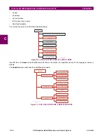
PDIS: phase distance, ground distance
•
PIOC: phase instantaneous overcurrent, neutral instantaneous overcurrent, ground instantaneous overcurrent, nega-
tive-sequence instantaneous overcurrent.
•
PTOC: phase time overcurrent, neutral time overcurrent, ground time overcurrent, negative-sequence time overcur-
rent, neutral directional overcurrent, negative-sequence directional overcurrent
•
PTUV: phase undervoltage, auxiliary undervoltage, third harmonic neutral undervoltage
•
PTOV: phase overvoltage, neutral overvoltage, auxiliary overvoltage, negative sequence overvoltage
•
RBRF: breaker failure
•
RREC: autoreclosure
•
RPSB: power swing detection
•
RFLO: fault locator
•
XCBR: breaker control
•
XSWI: circuit switch
•
CSWI: switch controller
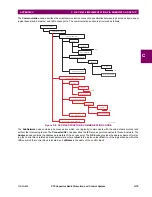
The protection elements listed above contain
start
(pickup) and
operate
flags. For example, the start flag for PIOC1 is
PIOC1.ST.Str.general. The operate flag for PIOC1 is PIOC1.ST.Op.general. For the C70 protection elements, these flags
take their values from the pickup and operate FlexLogic™ operands for the corresponding element.
Some protection elements listed above contain directional start values. For example, the directional start value for PDIS1 is
PDIS1.ST.Str.dirGeneral. This value is built from the directional FlexLogic™ operands for the element.
The RFLO logical node contains the measurement of the distance to fault calculation in kilometers. This value originates in
the fault locator function.
The XCBR logical node is directly associated with the breaker control feature.
•
XCBR1.ST.Loc: This is the state of the XCBR1 local/remote switch. A setting is provided to assign a FlexLogic™ oper-
and to determine the state. When local mode is true, IEC 61850 client commands will be rejected.
•
XCBR1.ST.Opcnt: This is an operation counter as defined in IEC 61850. Command settings are provided to allow the
counter to be cleared.
•
XCBR1.ST.Pos: This is the position of the breaker. The breaker control FlexLogic™ operands are used to determine
this state. If the breaker control logic indicates that the breaker, or any single pole of the breaker, is closed, then the
breaker position state is “on”. If the breaker control logic indicates that the breaker is open, then the breaker position
state is “off”.
•
XCBR1.ST.BlkOpn: This is the state of the block open command logic. When true, breaker open commands from IEC
61850 clients will be rejected.
•
XCBR1.ST.BlkCls: This is the state of the block close command logic. When true, breaker close commands from IEC
61850 clients will be rejected.
•
XCBR1.CO.Pos: This is where IEC 61850 clients can issue open or close commands to the breaker. SBO control with
normal security is the only supported IEC 61850 control model.
•
XCBR1.CO.BlkOpn: This is where IEC 61850 clients can issue block open commands to the breaker. Direct control
with normal security is the only supported IEC 61850 control model.
•
XCBR1.CO.BlkCls: This is where IEC 61850 clients can issue block close commands to the breaker. Direct control
with normal security is the only supported IEC 61850 control model.
Содержание UR Series C70
Страница 2: ......
Страница 10: ...x C70 Capacitor Bank Protection and Control System GE Multilin TABLE OF CONTENTS ...
Страница 30: ...1 20 C70 Capacitor Bank Protection and Control System GE Multilin 1 5 USING THE RELAY 1 GETTING STARTED 1 ...
Страница 124: ...4 30 C70 Capacitor Bank Protection and Control System GE Multilin 4 3 FACEPLATE INTERFACE 4 HUMAN INTERFACES 4 ...
Страница 344: ...5 220 C70 Capacitor Bank Protection and Control System GE Multilin 5 10 TESTING 5 SETTINGS 5 ...
Страница 396: ...8 18 C70 Capacitor Bank Protection and Control System GE Multilin 8 3 ENERVISTA SECURITY MANAGEMENT SYSTEM 8 SECURITY 8 ...
Страница 414: ...9 18 C70 Capacitor Bank Protection and Control System GE Multilin 9 1 OVERVIEW 9 THEORY OF OPERATION 9 ...
Страница 436: ...10 22 C70 Capacitor Bank Protection and Control System GE Multilin 10 4 SETTING EXAMPLE 10 APPLICATION OF SETTINGS 10 ...
Страница 547: ...GE Multilin C70 Capacitor Bank Protection and Control System B 79 APPENDIX B B 4 MEMORY MAPPING B ...
Страница 548: ...B 80 C70 Capacitor Bank Protection and Control System GE Multilin B 4 MEMORY MAPPING APPENDIXB B ...
Страница 586: ...D 10 C70 Capacitor Bank Protection and Control System GE Multilin D 1 OVERVIEW APPENDIXD D ...
Страница 598: ...E 12 C70 Capacitor Bank Protection and Control System GE Multilin E 2 DNP POINT LISTS APPENDIXE E ...

