10-12
C70 Capacitor Bank Protection and Control System
GE Multilin
10.4 SETTING EXAMPLE
10 APPLICATION OF SETTINGS
10
10.4SETTING EXAMPLE
10.4.1 DESCRIPTION
Consider protection of a capacitor bank with the following characteristics:
•
V
LL
= 138 kV fuseless.
•
Q
B
= 21 Mvar.
•
Two parallel strings (
S
= 2) in each phase with
N
= 7 capacitor units rated
Q
C
= 500 kvar,
V
C
= 11.62 kV.
•
Each capacitor unit consisting of
n
= 6 series capacitors.
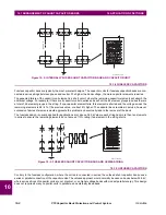
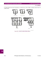
Refer to the diagram below for details. Phase capacitors are connected to ground through a neutral capacitor rated
Q
CN
= 167 kvar,
V
CN
= 0.825 kV.
Figure 10–12: SAMPLE CAPACITOR BANK CONFIGURATION
Based on the bank configuration, CT connections, and VTs connections, a C70 model is chosen with three CT/VT modules:
two type 8L modules (in slots F and U) and one type 8V module (in slot M) to provide following protection functionality.
•
Negative-sequence instantaneous overcurrent (ANSI 50_2) to provide fast backup protection against arcing within
capacitor bank.
•
Phase overvoltage (ANSI 59B) to provide protection against overvoltages.
•
Bank overcurrent protection, phase instantaneous overcurrent (ANSI 50P), neutral instantaneous overcurrent (ANSI
50N) and phase time overcurrent (ANSI 51P) to provide protection against major faults within the capacitor bank.
•
Bank undervoltage (ANSI 27P) to detect loss of bus voltage and trip the bank.
•
Voltage differential (ANSI 87V) to detect failure of one or more capacitor elements in a given string. Three voltage dif-
ferential elements can be set for this application: one between two tap voltages (ANSI 87V-1) and two between the bus
voltage and tap voltage in both strings (ANSI 87V-2 and 87V-3).
•
Phase current unbalance (ANSI 60P) to detect failure of one or more capacitor elements in a given string.
10.4.2 VT AND CT SETUP
The CT and VT connections are shown in the figure above. The CT channels are connected as follows.
•
The type 8L CT/VT module F1 to F3 three-phase CT channels are connected to the bus side three-phase CTs with a
120 / 5 A ratio.
F1-3
F5-7
59B
87V
51N
C70 CAPACITOR BANK RELAY
U1-3
60P
(A)
60P
(B)
60P
(C)
138 kV
138 kV/
0.115 kV/
500 kvar
11620 V
120/5A
50/5A
50_2
50P
51P
27P
1250/250 V
167KVAR,
825V
`
L4-7
L1-3
3
834764A1.CDR
Содержание UR Series C70
Страница 2: ......
Страница 10: ...x C70 Capacitor Bank Protection and Control System GE Multilin TABLE OF CONTENTS ...
Страница 30: ...1 20 C70 Capacitor Bank Protection and Control System GE Multilin 1 5 USING THE RELAY 1 GETTING STARTED 1 ...
Страница 124: ...4 30 C70 Capacitor Bank Protection and Control System GE Multilin 4 3 FACEPLATE INTERFACE 4 HUMAN INTERFACES 4 ...
Страница 344: ...5 220 C70 Capacitor Bank Protection and Control System GE Multilin 5 10 TESTING 5 SETTINGS 5 ...
Страница 396: ...8 18 C70 Capacitor Bank Protection and Control System GE Multilin 8 3 ENERVISTA SECURITY MANAGEMENT SYSTEM 8 SECURITY 8 ...
Страница 414: ...9 18 C70 Capacitor Bank Protection and Control System GE Multilin 9 1 OVERVIEW 9 THEORY OF OPERATION 9 ...
Страница 436: ...10 22 C70 Capacitor Bank Protection and Control System GE Multilin 10 4 SETTING EXAMPLE 10 APPLICATION OF SETTINGS 10 ...
Страница 547: ...GE Multilin C70 Capacitor Bank Protection and Control System B 79 APPENDIX B B 4 MEMORY MAPPING B ...
Страница 548: ...B 80 C70 Capacitor Bank Protection and Control System GE Multilin B 4 MEMORY MAPPING APPENDIXB B ...
Страница 586: ...D 10 C70 Capacitor Bank Protection and Control System GE Multilin D 1 OVERVIEW APPENDIXD D ...
Страница 598: ...E 12 C70 Capacitor Bank Protection and Control System GE Multilin E 2 DNP POINT LISTS APPENDIXE E ...

