


4-24
C70 Capacitor Bank Protection and Control System
GE Multilin
4.3 FACEPLATE INTERFACE
4 HUMAN INTERFACES
4
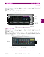
e) CONTROL OF ONE BREAKER
For this application the relay is connected and programmed for breaker 1 only. Operation for this application is identical to
that described above for two breakers.
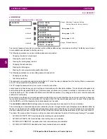
4.3.7 MENUS
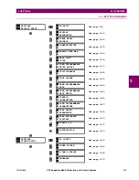
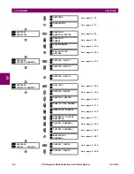
a) NAVIGATION
Press the MENU key to select the desired header display page (top-level menu). The header title appears momentarily fol-
lowed by a header display page menu item. Each press of the MENU key advances through the following main heading
pages:
•
Actual values.
•
Settings.
•
Commands.
•
Targets.
•
User displays (when enabled).
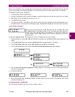
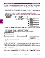
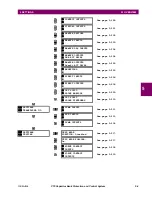
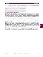
ENTER COMMAND
PASSWORD
This message appears when the USER 1, USER 2, or USER 3 key is pressed and a
COMMAND PASSWORD
is required; i.e. if
COMMAND PASSWORD
is enabled and no com-
mands have been issued within the last 30 minutes.
Press USER 1
To Select Breaker
This message appears if the correct password is entered or if none is required. This mes-
sage will be maintained for 30 seconds or until the USER 1 key is pressed again.
BKR1-(Name) SELECTED
USER 2=CLS/USER 3=OP
This message is displayed after the USER 1 key is pressed for the second time. Three
possible actions can be performed from this state within 30 seconds as per items
(1)
,
(2)
and
(3)
below:
(1)
USER 2 OFF/ON
To Close BKR1-(Name)
If the USER 2 key is pressed, this message appears for 20 seconds. If the USER 2 key is
pressed again within that time, a signal is created that can be programmed to operate an
output relay to close breaker 1.
(2)
USER 3 OFF/ON
To Open BKR1-(Name)
If the USER 3 key is pressed, this message appears for 20 seconds. If the USER 3 key is
pressed again within that time, a signal is created that can be programmed to operate an
output relay to open breaker 1.
(3)
BKR2-(Name) SELECTED
USER 2=CLS/USER 3=OP
If the USER 1 key is pressed at this step, this message appears showing that a different
breaker is selected. Three possible actions can be performed from this state as per
(1)
,
(2)
and
(3)
. Repeatedly pressing the USER 1 key alternates between available breakers.
Pressing keys other than USER 1, 2 or 3 at any time aborts the breaker control function.
Содержание UR Series C70
Страница 2: ......
Страница 10: ...x C70 Capacitor Bank Protection and Control System GE Multilin TABLE OF CONTENTS ...
Страница 30: ...1 20 C70 Capacitor Bank Protection and Control System GE Multilin 1 5 USING THE RELAY 1 GETTING STARTED 1 ...
Страница 124: ...4 30 C70 Capacitor Bank Protection and Control System GE Multilin 4 3 FACEPLATE INTERFACE 4 HUMAN INTERFACES 4 ...
Страница 344: ...5 220 C70 Capacitor Bank Protection and Control System GE Multilin 5 10 TESTING 5 SETTINGS 5 ...
Страница 396: ...8 18 C70 Capacitor Bank Protection and Control System GE Multilin 8 3 ENERVISTA SECURITY MANAGEMENT SYSTEM 8 SECURITY 8 ...
Страница 414: ...9 18 C70 Capacitor Bank Protection and Control System GE Multilin 9 1 OVERVIEW 9 THEORY OF OPERATION 9 ...
Страница 436: ...10 22 C70 Capacitor Bank Protection and Control System GE Multilin 10 4 SETTING EXAMPLE 10 APPLICATION OF SETTINGS 10 ...
Страница 547: ...GE Multilin C70 Capacitor Bank Protection and Control System B 79 APPENDIX B B 4 MEMORY MAPPING B ...
Страница 548: ...B 80 C70 Capacitor Bank Protection and Control System GE Multilin B 4 MEMORY MAPPING APPENDIXB B ...
Страница 586: ...D 10 C70 Capacitor Bank Protection and Control System GE Multilin D 1 OVERVIEW APPENDIXD D ...
Страница 598: ...E 12 C70 Capacitor Bank Protection and Control System GE Multilin E 2 DNP POINT LISTS APPENDIXE E ...


