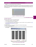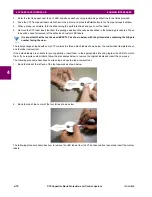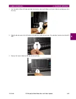
GE Multilin
C70 Capacitor Bank Protection and Control System
4-25
4 HUMAN INTERFACES
4.3 FACEPLATE INTERFACE
4
b) HIERARCHY
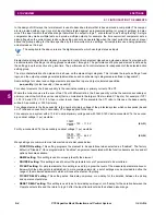
The setting and actual value messages are arranged hierarchically. The header display pages are indicated by double
scroll bar characters (
), while sub-header pages are indicated by single scroll bar characters (
). The header display
pages represent the highest level of the hierarchy and the sub-header display pages fall below this level. The MESSAGE
UP and DOWN keys move within a group of headers, sub-headers, setting values, or actual values. Continually pressing
the MESSAGE RIGHT key from a header display displays specific information for the header category. Conversely, contin-
ually pressing the MESSAGE LEFT key from a setting value or actual value display returns to the header display.
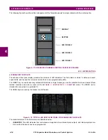
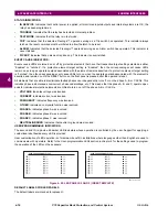
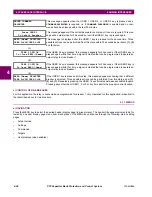
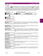
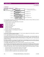
c) EXAMPLE MENU NAVIGATION
HIGHEST LEVEL
LOWEST LEVEL (SETTING VALUE)
SETTINGS
PRODUCT SETUP
PASSWORD
SECURITY
ACCESS LEVEL:
Restricted
SETTINGS
SYSTEM SETUP
ACTUAL VALUES
STATUS
Press the MENU key until the header for the first Actual Values page appears. This
page contains system and relay status information. Repeatedly press the MESSAGE
keys to display the other actual value headers.
Ø
SETTINGS
PRODUCT SETUP
Press the MENU key until the header for the first page of Settings appears. This page
contains settings to configure the relay.
Ø
SETTINGS
SYSTEM SETUP
Press the MESSAGE DOWN key to move to the next Settings page. This page con-
tains settings for System Setup. Repeatedly press the MESSAGE UP and DOWN
keys to display the other setting headers and then back to the first Settings page
header.
Ø
PASSWORD
SECURITY
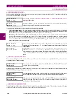
From the Settings page one header (Product Setup), press the MESSAGE RIGHT
key once to display the first sub-header (Password Security).
Ø
ACCESS LEVEL:
Restricted
Press the MESSAGE RIGHT key once more and this will display the first setting for
Password Security. Pressing the MESSAGE DOWN key repeatedly will display the
remaining setting messages for this sub-header.
Ø
PASSWORD
SECURITY
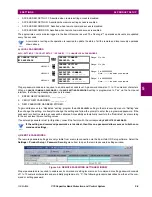
Press the MESSAGE LEFT key once to move back to the first sub-header message.
Ø
DISPLAY
PROPERTIES
Pressing the MESSAGE DOWN key will display the second setting sub-header asso-
ciated with the Product Setup header.
Ø
FLASH MESSAGE
TIME: 1.0 s
Press the MESSAGE RIGHT key once more and this will display the first setting for
Display Properties.
Ø
DEFAULT MESSAGE
INTENSITY: 25%
To view the remaining settings associated with the Display Properties subheader,
repeatedly press the MESSAGE DOWN key. The last message appears as shown.
Содержание UR Series C70
Страница 2: ......
Страница 10: ...x C70 Capacitor Bank Protection and Control System GE Multilin TABLE OF CONTENTS ...
Страница 30: ...1 20 C70 Capacitor Bank Protection and Control System GE Multilin 1 5 USING THE RELAY 1 GETTING STARTED 1 ...
Страница 124: ...4 30 C70 Capacitor Bank Protection and Control System GE Multilin 4 3 FACEPLATE INTERFACE 4 HUMAN INTERFACES 4 ...
Страница 344: ...5 220 C70 Capacitor Bank Protection and Control System GE Multilin 5 10 TESTING 5 SETTINGS 5 ...
Страница 396: ...8 18 C70 Capacitor Bank Protection and Control System GE Multilin 8 3 ENERVISTA SECURITY MANAGEMENT SYSTEM 8 SECURITY 8 ...
Страница 414: ...9 18 C70 Capacitor Bank Protection and Control System GE Multilin 9 1 OVERVIEW 9 THEORY OF OPERATION 9 ...
Страница 436: ...10 22 C70 Capacitor Bank Protection and Control System GE Multilin 10 4 SETTING EXAMPLE 10 APPLICATION OF SETTINGS 10 ...
Страница 547: ...GE Multilin C70 Capacitor Bank Protection and Control System B 79 APPENDIX B B 4 MEMORY MAPPING B ...
Страница 548: ...B 80 C70 Capacitor Bank Protection and Control System GE Multilin B 4 MEMORY MAPPING APPENDIXB B ...
Страница 586: ...D 10 C70 Capacitor Bank Protection and Control System GE Multilin D 1 OVERVIEW APPENDIXD D ...
Страница 598: ...E 12 C70 Capacitor Bank Protection and Control System GE Multilin E 2 DNP POINT LISTS APPENDIXE E ...

