GE Multilin
C70 Capacitor Bank Protection and Control System
5-127
5 SETTINGS
5.6 GROUPED ELEMENTS
5
•
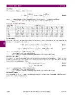
CUR UNBALCE 1 STG 1A PICKUP
to
CUR UNBALCE 1 STG 4C PICKUP
: These settings specify pickup thresholds
for stages 1 through 4 in phases A through C in per-units (pu) of the nominal current of the differential source. A value
of 1 pu is the nominal secondary current, or the nominal primary current, respectively, as configured under the differen-
tial source of this function.
•
CUR UNBALCE 1 STG 1 PKP DELAY
to
CUR UNBALCE 1 STG 4 PKP DELAY
: This setting specifies the pickup
time delay, individually per each stage of alarming/tripping. Note that each of the twelve comparators (four stages in
three phases) uses an individual timer, but settings for these timers are controlled individually per each stage, not per
phase. The timers use a common drop out time delay specified by the next setting.
•
CUR UNBALCE 1 DPO DELAY
: This setting controls a drop out delay for the operate FlexLogic™ operands. Note that
individual stages apply individually configurable pickup delays, but use this common drop out delay.
•
CUR UNBL 1 BLK STG1
to
CUR UNBL 1 BLK STG4
: These settings are used to block the function on a per-stage
basis when required. At minimum this function shall be blocked when the two banks are not paralleled. Note that when
unblocked, the function becomes operational after five cycles of intentional delay. High-set instantaneous protection on
energization can be provided by a separate instantaneous overcurrent function.
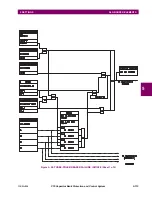
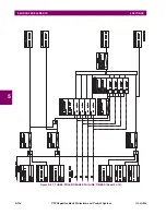
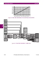
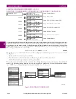
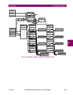
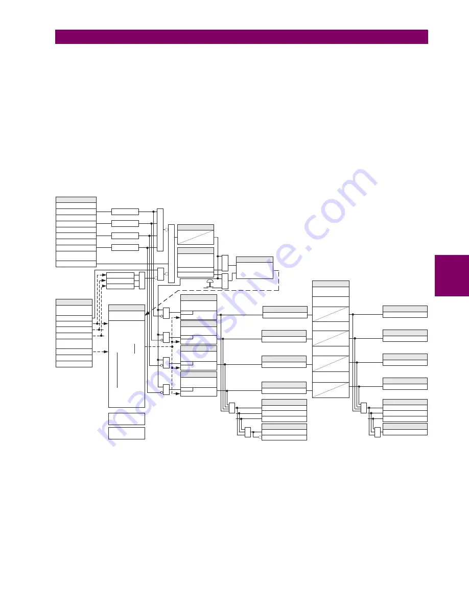
Figure 5–57: PHASE CURRENT UNBALANCE SCHEME LOGIC
IA_op > PICKUP
t
PKP
t
DPO
t
PKP
t
DPO
t
PKP
t
DPO
SETTINGS
CUR UNBALCE 1
BANK SOURCE:
IA
IB
IC
CUR UNBALCE 1 DIF
SOURCE:
IA_dif
IB_dif
IC_dif
SETTINGS
CUR UNBALCE 1
INHNT FACTOR A:
SETTING
CUR UNBALCE 1 STG
1A PICKUP:
SETTING
CUR UNBALCE 1 STG
2A PICKUP:
SETTING
CUR UNBALCE 1 STG
3A PICKUP:
SETTING
CUR UNBALCE 1 STG
4A PICKUP:
CUR BAL 1 STG 1A PKP
FLEXLOGIC OPERAND
CUR BAL 1 STG 2A PKP
FLEXLOGIC OPERAND
CUR BAL 1 STG 3A PKP
FLEXLOGIC OPERAND
CUR BAL 1 STG 4A PKP
FLEXLOGIC OPERAND
t
PKP
t
DPO
TIMERS
CUR UNBALCE 1 STG
1 PKP DELAY:
CUR UNBALCE 1 STG
2 PKP DELAY:
CUR UNBALCE 1 STG
3 PKP DELAY:
CUR UNBALCE 1 STG
4 PKP DELAY:
CUR BAL 1 STG 1A OP
FLEXLOGIC OPERAND
CUR BAL 1 STG 2A OP
FLEXLOGIC OPERAND
CUR BAL 1 STG 3A OP
FLEXLOGIC OPERAND
CUR BAL 1 STG 4A OP
FLEXLOGIC OPERAND
CUR BAL 1 PKP B
FLEXLOGIC OPERANDS
CUR UNBALCE 1 DPO
DELAY:
CUR BAL 1 PKP A
CUR BAL 1 PKP C
OR
FLEXLOGIC OPERAND
CUR BAL 1 PKP
OR
CUR BAL 1 OP B
FLEXLOGIC OPERANDS
CUR BAL 1 OP A
CUR BAL 1 OP C
OR
FLEXLOGIC OPERAND
CUR BAL 1 OP
OR
CUR BAL 1 DPO
PHASE C
5 cycles
0
TIMER
RUN 60P FUNCTION
PHASE B
COMMANDS
AUTO-SETTING
PROCEDURE
AND
SETTING
COMMANDS/ CUR
UNBALACE 1 AUTO-
SETTING:
Auto
WRITE A NEW SETTING
AND
IC_mag > 0.25pu
IB_mag > 0.25pu
IA_mag > 0.25pu
SETTINGS
CUR UNBALCE 1
FUNCTION:
Enabled = 1
CUR UNBL 1 BLK STG1:
Off = 0
CUR UNBL 1 BLK STG2:
Off = 0
CUR UNBL 1 BLK STG3:
Off = 0
CUR UNBL 1 BLK STG4:
Off = 0
AND
INHIBIT STAGE 1
INHIBIT STAGE 3
INHIBIT STAGE 4
INHIBIT STAGE 2
Apply?
RUN
RUN
IA_op > PICKUP
RUN
IA_op > PICKUP
RUN
IA_op > PICKUP
RUN
AND
AND
AND
AND
Manual
AND
834729A2.CDR
PHASE CT "None" = 0
AND
AND
⎟ ⎠
⎞
⎜ ⎝
⎛
×
×
−
×
=
A
bank
dif
f
bank
A
A
dif
f
A
op
I
n
n
k
I
I
_
_
e
diff_sour
c
secondar
y_
_
mag
CT
1
Содержание UR Series C70
Страница 2: ......
Страница 10: ...x C70 Capacitor Bank Protection and Control System GE Multilin TABLE OF CONTENTS ...
Страница 30: ...1 20 C70 Capacitor Bank Protection and Control System GE Multilin 1 5 USING THE RELAY 1 GETTING STARTED 1 ...
Страница 124: ...4 30 C70 Capacitor Bank Protection and Control System GE Multilin 4 3 FACEPLATE INTERFACE 4 HUMAN INTERFACES 4 ...
Страница 344: ...5 220 C70 Capacitor Bank Protection and Control System GE Multilin 5 10 TESTING 5 SETTINGS 5 ...
Страница 396: ...8 18 C70 Capacitor Bank Protection and Control System GE Multilin 8 3 ENERVISTA SECURITY MANAGEMENT SYSTEM 8 SECURITY 8 ...
Страница 414: ...9 18 C70 Capacitor Bank Protection and Control System GE Multilin 9 1 OVERVIEW 9 THEORY OF OPERATION 9 ...
Страница 436: ...10 22 C70 Capacitor Bank Protection and Control System GE Multilin 10 4 SETTING EXAMPLE 10 APPLICATION OF SETTINGS 10 ...
Страница 547: ...GE Multilin C70 Capacitor Bank Protection and Control System B 79 APPENDIX B B 4 MEMORY MAPPING B ...
Страница 548: ...B 80 C70 Capacitor Bank Protection and Control System GE Multilin B 4 MEMORY MAPPING APPENDIXB B ...
Страница 586: ...D 10 C70 Capacitor Bank Protection and Control System GE Multilin D 1 OVERVIEW APPENDIXD D ...
Страница 598: ...E 12 C70 Capacitor Bank Protection and Control System GE Multilin E 2 DNP POINT LISTS APPENDIXE E ...

