GE Multilin
C70 Capacitor Bank Protection and Control System
3-39
3 HARDWARE
3.4 MANAGED ETHERNET SWITCH MODULES
3
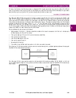
The wiring for the managed Ethernet switch module is shown below.
Figure 3–43: MANAGED ETHERNET SWITCH MODULE WIRING
3.4.3 MANAGED SWITCH LED INDICATORS
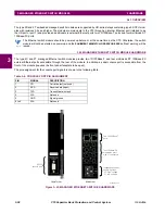
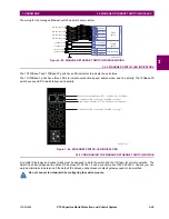
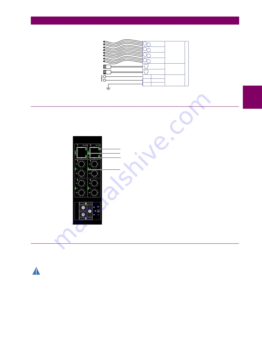
The 10/100Base-T and 100Base-FX ports have LED indicators to indicate the port status.
The 10/100Base-T ports have three LEDs to indicate connection speed, duplex mode, and link activity. The 100Base-FX
ports have one LED to indicate linkup and activity.
Figure 3–44: ETHERNET SWITCH LED INDICATORS
3.4.4 CONFIGURING THE MANAGED ETHERNET SWITCH MODULE
A suitable IP/gateway and subnet mask must be assigned to both the switch and the UR relay for correct operation. The
Switch has been shipped with a default IP address of 192.168.1.2 and a subnet mask of 255.255.255.0. Consult your net-
work administrator to determine if the default IP address, subnet mask or default gateway needs to be modified.
Do not connect to network while configuring the switch module.
842835A1.CDR
100Base-FX
100Base-FX
Tx1
Rx1
Tx2
Rx2
GROUND
+
―
W1a
W2b
W1a
Power supply
Copper
ports
CPU
2S / 2T
MM fiber optic cable
MM fiber optic cable
10/100Base-T
10/100Base-T
100Base-FX
Tx1
Rx1
100Base-FX
Tx1
Rx1
Fiber
ports
MM fiber optic cable
MM fiber optic cable
+
–
100Base-T cable
100Base-T cable
110 to 250 V DC
100 to 240 V AC
842868A2.CDR
Connection speed indicator (OFF = 10 Mbps; ON = 100 Mbps)
Link indicator (ON = link active; FLASHING = activity)
Duplex mode indicator (OFF = half-duplex; ON = full-duplex)
Link indicator (ON = link active; FLASHING = activity)
CAUTION
Содержание UR Series C70
Страница 2: ......
Страница 10: ...x C70 Capacitor Bank Protection and Control System GE Multilin TABLE OF CONTENTS ...
Страница 30: ...1 20 C70 Capacitor Bank Protection and Control System GE Multilin 1 5 USING THE RELAY 1 GETTING STARTED 1 ...
Страница 124: ...4 30 C70 Capacitor Bank Protection and Control System GE Multilin 4 3 FACEPLATE INTERFACE 4 HUMAN INTERFACES 4 ...
Страница 344: ...5 220 C70 Capacitor Bank Protection and Control System GE Multilin 5 10 TESTING 5 SETTINGS 5 ...
Страница 396: ...8 18 C70 Capacitor Bank Protection and Control System GE Multilin 8 3 ENERVISTA SECURITY MANAGEMENT SYSTEM 8 SECURITY 8 ...
Страница 414: ...9 18 C70 Capacitor Bank Protection and Control System GE Multilin 9 1 OVERVIEW 9 THEORY OF OPERATION 9 ...
Страница 436: ...10 22 C70 Capacitor Bank Protection and Control System GE Multilin 10 4 SETTING EXAMPLE 10 APPLICATION OF SETTINGS 10 ...
Страница 547: ...GE Multilin C70 Capacitor Bank Protection and Control System B 79 APPENDIX B B 4 MEMORY MAPPING B ...
Страница 548: ...B 80 C70 Capacitor Bank Protection and Control System GE Multilin B 4 MEMORY MAPPING APPENDIXB B ...
Страница 586: ...D 10 C70 Capacitor Bank Protection and Control System GE Multilin D 1 OVERVIEW APPENDIXD D ...
Страница 598: ...E 12 C70 Capacitor Bank Protection and Control System GE Multilin E 2 DNP POINT LISTS APPENDIXE E ...


