background image

1.7  H: Terminal Functions

YASKAWA ELECTRIC SIEP C710606 10A YASKAWA AC Drive - V1000 PRELIM. Programming Manual

 149

Pa

ra

m

et

er D

et

ai

ls

1

Setting 1A: Accel/Decel Time Selection 2

Used to select accel/decel times 3 and 4 in combination with the Accel/Decel Time Selection 
1 command. Refer to 

C1-01 to C1-08: Accel/Decel Times 1 to 4 on page 77

 for details.

Setting 1B: Program Lockout

When an input is programmed for Program Lockout, parameters values can be monitored 
but not changed as long as this input is open.

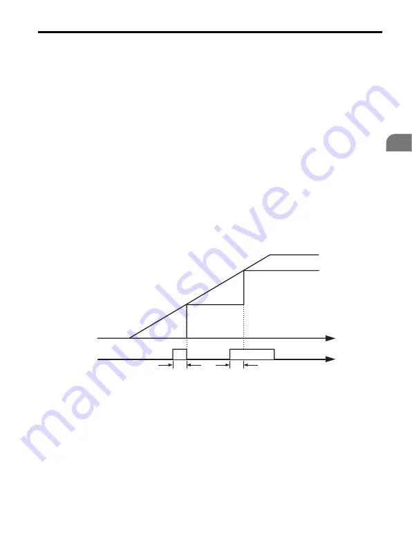
Setting 1E: Analog Frequency Reference Sample / Hold

This function allows the user to sample an analog frequency reference signal being input to 
terminal A1 or A2 and hold the frequency reference at the sampled level. Once the Analog 
Frequency Reference Sample / Hold function is held for at least 100 ms, the drive reads the 
analog input and changes the frequency reference to the newly sampled speed as illustrated 
in 

Figure 1.51

.

When the power is shut off and the sampled analog frequency reference is cleared, the 
frequency reference is reset to 0.

Figure 1.51  

Figure 1.51  Analog Frequency Reference Sample/Hold

An oPE03 error will occur when one of the following functions is used simultaneously with 
the Analog Frequency Reference Sample / Hold function.

• Hold Accel/Decel Stop (setting: A)
• Up command, Down command (setting: 10, 11)
• Offset Frequency (setting: 44 to 46)
• Up or Down functions (setting: 75, 76)


Frequency

reference

ON (closed)

OFF (open)

Time

100 ms

Referenece

Sample Hold Input

Analog signal

100 ms

Summary of Contents for OYMC V1000

Page 1: ...nual Type VZA Model 200 V Class Three Phase Input 0 1 to 15 0 kW 200 V Class Single Phase Input 0 1 to 4 0 kW 400 V Class Three Phase Input 0 2 to 15 0 kW To properly use the product read this manual...

Page 2: ...2 YASKAWA ELECTRIC SIEP C710606 10A YASKAWA AC Drive V1000 PRELIM Programming Manual...

Page 3: ...mentation 10 Symbols 10 Terms and Abbreviations 11 i 2 General Safety 12 Supplemental Safety Information 12 Safety Messages 14 Drive Label Warnings 17 Warranty Information 17 1 PARAMETER DETAILS 19 1...

Page 4: ...Hold and Up Down 2 Function 100 d7 Offset Frequencies 108 1 5 E Motor Parameters 109 E1 V f Characteristics 109 E2 Motor 1 Parameters 116 E3 V f Characteristics for Motor 2 119 E4 Motor 2 Parameters 1...

Page 5: ...to Line Resistance Online Tuning 230 n8 PM Motor Control 230 1 10 o Operator Related Settings 234 o1 Display Settings and Selections 234 o2 Operator Key Selections 236 o4 Maintenance Monitor Settings...

Page 6: ...6 Observing the Drive Operation 266 Controlling the Drive 266 2 6 Communications Timing 267 For Command Messages from Master to Drive 267 For Response Messages from Drive to Master 268 2 7 Message For...

Page 7: ...ing 306 d References 311 E Motor Parameters 316 F Options 323 H Parameters Multi Function Terminals 327 L Protection Function 339 n Advanced Performance Set Up 353 o Operator Related Parameters 357 q...

Page 8: ...8 YASKAWA ELECTRIC SIEP C710606 10A YASKAWA AC Drive V1000 PRELIM Programming Manual INDEX 393...

Page 9: ...al 9 Preface General Safety This section provides safety messages pertinent to this product that if not heeded may result in fatality personal injury or equipment damage OYMC is not responsible for th...

Page 10: ...the end user OYMC offers an express warranty only as to the quality of its products in conforming to standards and specifications published in the OYMC manual NO OTHER WARRANTY EXPRESS OR IMPLIED IS O...

Page 11: ...e V1000 PRELIM Programming Manual 11 t Preface General Safety i Terms and Abbreviations TERMS TERMS TERMS Drive OYMC V1000 Series Drive PM motor Synchronous motor an abbreviation for IPM motor or SPM...

Page 12: ...may be changed without notice to improve the product and or the manual When ordering a new copy of the manual due to damage or loss contact your OYMC representative or the nearest OYMC sales office a...

Page 13: ...also be indicated by a bold key word embedded in the text followed by an italicized safety message NOTICE will also be indicated by a bold key word embedded in the text followed by an italicized safe...

Page 14: ...indicator LED will extinguish when the DC bus voltage is below 50 Vdc To prevent electric shock wait at least five minutes after all indicators are OFF and measure the DC bus voltage level to confirm...

Page 15: ...r serious injury Maintenance inspection and replacement of parts must be performed only by authorized personnel familiar with installation adjustment and maintenance of AC drives Do not remove covers...

Page 16: ...within the drive Do not operate damaged equipment Failure to comply could result in further damage to the equipment Do not connect or operate any equipment with visible damage or missing parts Install...

Page 17: ...tomers who intend to use the product described in this manual for devices or systems relating to transportation health care space aviation atomic power electric power or in Risk of electric shock WARN...

Page 18: ...office This product has been manufactured under strict quality control guidelines However if this product is to be installed in any location where failure of this product could involve or result in a...

Page 19: ...NITIALIZATION 20 1 2 B APPLICATION 35 1 3 C TUNING 77 1 4 D REFERENCE SETTINGS 94 1 5 E MOTOR PARAMETERS 109 1 6 F OPTION SETTINGS 128 1 7 H TERMINAL FUNCTIONS 139 1 8 L PROTECTION FUNCTIONS 185 1 9 N...

Page 20: ...ameters can be viewed and edited Notes on Parameter Access If the drive parameters are password protected by A1 04 parameters A1 00 through A1 03 A1 06 and all A2 parameters can not be modified If a d...

Page 21: ...To clear the user defined default values set parameter o2 03 to 2 Setting 2220 2 Wire Initialization Resets all parameters back to their original default settings with digital inputs S1 and S2 config...

Page 22: ...gh A2 33 The instructions below demonstrate how to set a new password Here the password set is 1234 An explanation follows on how to enter the password to unlock the parameters No Parameter Name A1 02...

Page 23: ...2 Scroll to the Parameter Setup display and press 3 Scroll to the right by pressing 4 Select the flashing digits by pressing 5 Select A1 04 by pressing 6 Press the key while holding down at the same...

Page 24: ...lues cannot be changed 4 Press to return to the first display Step Display Result 1 Press to enter the parameter setup display 2 Press to select the flashing digits as shown 01 flashes 3 Press to scro...

Page 25: ...nged are assigned to the list of Preferred Parameters A2 01 through A2 16 These can be accessed in the Setup Mode and provide a fast application adjustment without scrolling through many menus The fol...

Page 26: ...0 E1 08 Mid Output Frequency Voltage 50 0 L2 01 Momentary Power Loss Operation Selection 1 Enabled L3 04 Stall Prevention Selection during Deceleration 1 Enabled No Parameter Name No Parameter Name b...

Page 27: ...A1 02 Control Method Selection 0 V f Control b1 04 Reverse Operation Selection 1 Reverse Prohibited C6 01 Duty Selection 1 Normal Duty E1 03 V f Pattern Selection 0FH E1 07 Mid Output Frequency 30 0 E...

Page 28: ...rt if power returns prior to control power supply shut down L8 03 Overheat Pre Alarm Operation Selection 4 Operation at lower speed L8 38 Carrier Frequency Reduction 2 Enabled across entire frequency...

Page 29: ...lection 0FH L2 01 Momentary Power Loss Operation Selection 1 Enabled L3 04 Stall Prevention Selection during Deceleration 1 Enabled No Parameter Name No Parameter Name b1 01 Frequency Reference Select...

Page 30: ...dth 0 0 Hz L6 01 Torque Detection Selection 1 8 UL3 at RUN Fault L6 02 Torque Detection Level 1 5 L6 03 Torque Detection Time 1 0 5 s L8 05 Input Phase Loss Protection Selection 1 Enabled L8 07 Output...

Page 31: ...ource of the frequency reference is assigned to the control circuit terminals b1 01 1 4 A sequence to open and close the holding brake appears in the diagram below Brake Open Close 1 This is the setti...

Page 32: ...y Reference 3 50 0 Hz H1 05 Multi Function Digital Input Terminal S5 Function 3 Multi Step Speed 1 H1 06 Multi Function Digital Input Terminal S6 Function 4 Multi Step Speed 2 H2 02 Terminals P1 Funct...

Page 33: ...Digital Input If a digital input is programmed for FBD s enable disable H1 9F FBD s will be enabled when the input is disabled A2 Preferred Parameters A2 01 to A2 32 Preferred Parameters The user can...

Page 34: ...determines whether or not parameters that have been edited are saved to the Preferred Parameters A2 17 to A2 32 for quick easy access Setting 0 Do not save list of recently view parameters To manually...

Page 35: ...requency reference can be input by switching between the multi speed references in the d1 parameters entering the frequency reference on the operator keypad Setting 1 Terminals analog input terminals...

Page 36: ...entering 0 into parameter H3 10 refer to H3 10 Terminal A2 Function Selection on page 176 Using Control Circuit Terminal A2 0 4 to 20 mA current input Connect input A2 to an external current source s...

Page 37: ...1 is set to 0 Digital operator for multi speed references set the terminal A2 function to auxiliary frequency H3 10 2 set one digital input to multi speed 1 H1 3 default for S5 The frequency reference...

Page 38: ...d for instructions on integrating the drive with the communication system Note If the frequency reference source is set for an option PCB b1 01 3 but an option board is not installed in 2CN an OPE05 O...

Page 39: ...and stop the motor The LED in the LO RE key will be on to indicate that the Run command is assigned to the operator The example below shows how the drive can be operated if b1 02 is set to 0 Table 1...

Page 40: ...ations on page 257 Setting 3 Option Card To issue the Run command via the communication option board set b1 02 to 3 and plug a communication option board into the 2CN port on the control PCB Refer to...

Page 41: ...to a complete stop To start the motor back up before it has stopped completely use DC Injection at start refer to Refer to b2 03 DC Injection Braking Time at Start on page 48 or Speed Search refer to...

Page 42: ...Braking Time Depending on Output Frequency Note If an overcurrent oC fault occurs during DC Injection Braking to stop lengthen the minimum baseblock time L2 03 until the fault no longer occurs Run com...

Page 43: ...Timer The time t value of C1 02 is determined by the output frequency when the Run command is removed and by the active deceleration time Figure 1 10 Figure 1 10 Run Wait Time Depending on Output Fre...

Page 44: ...e used H1 must be different than 65 66 7A 7B The Stall Prevention during stop must be deactivated L3 04 0 For regenerative loads a braking option might be necessary The overvoltage suppression must be...

Page 45: ...b1 07 can be used to determine how the Run command is treated in this case Setting 0 Run Command Must Be Cycled If the Run command is issued differently in the old and new control source e g old termi...

Page 46: ...Phase Order Setting 1 Switched Phase Order b1 15 Frequency Reference Selection 2 Refer to the detailed description for parameter b1 01 b1 16 Run Command Source 2 Refer to the detailed description for...

Page 47: ...ound the motor is safe prior to powering up the drive Failure to comply may cause injury b2 DC Injection Braking These parameters determine how the DC Injection Braking Short Circuit Braking feature o...

Page 48: ...an be used to stop a coasting motor before restarting it or to apply a braking torque at start Disabled when set to 0 00 s Note Before starting an uncontrolled rotating motor e g a fan motor driven by...

Page 49: ...e used in Open Loop Vector for PM motors By shorting all three motor phases it produces a braking torque in the motor and can be used to stop a coasting motor before starting it Parameter b2 12 sets t...

Page 50: ...d below followed by a description of all relevant parameters Speed Estimation Type Speed Search b3 24 1 This method can be used for a single motor connected to a drive It should not be utilized if the...

Page 51: ...ed Search is applied with the Run command b3 01 1 or if an External Search command is used It injects the DC current set in b3 06 to the motor and detects the speed by measuring the current feedback T...

Page 52: ...n operating motors smaller than 1 5 kW Speed Estimation can end up stopping smaller motors as it might not be able to detect the speed or rotation direction of such small motors Use Short circuit Brak...

Page 53: ...fter Power Loss Note After power is restored the drive waits until the time set to b3 05 has passed before performing Speed Search Thereby the Speed Search may start not at the end of L2 03 but even l...

Page 54: ...rent Detection Speed Search is not available when using Open Loop Vector Control for PM motors Increase the minimum baseblock time set to L2 03 if an overcurrent fault occurs when performing Speed Sea...

Page 55: ...ommand H1 8 or 9 N O and N C respectively is released b3 01 Speed Search Selection at Start Selects if Speed Search is automatically performed when a Run command is issued Setting 0 Disabled Speed Sea...

Page 56: ...ding enough time to operate the contactor When Speed Search at start is used b3 05 will serve as the lower limit of the minimum baseblock time L2 03 b3 06 Output Current 1 During Speed Search Sets the...

Page 57: ...performing Speed Estimation Speed Search The setting has no influence on Current Detection Speed Search b3 24 0 Setting 0 Disabled The drive uses the frequency reference to determine the direction of...

Page 58: ...Current Detection Type Speed Search b3 24 0 on page 52 and Speed Estimation Type Speed Search b3 24 1 on page 50 Setting 0 Current Detection Speed Search Setting 1 Speed Estimation Speed Search b3 25...

Page 59: ...es the timer function operation Figure 1 17 Figure 1 17 Timer Operation b5 PID Control The drive has a built in PID Proportional Integral Derivative controller that can be used for closed loop control...

Page 60: ...this to the PID input This way the D portion of a PID controller provides a braking action to the controller response and can reduce the tendency of oscillations and overshoot Be aware that D control...

Page 61: ...ed below Table 1 22 PID Feedback Sources Application Description Sensors Used Speed Control Machinery speed is fed back and adjusted to meet the target value Synchronous control is performed using spe...

Page 62: ...edback signal for differential feedback can come from the sources listed below The differential feedback function is automatically enabled when a differential feedback input is assigned Table 1 23 PID...

Page 63: ...nput Characteristic H1 35 1 0 PID Soft Starter b5 17 PID SFS Cancel DI H1 34 PID Input U5 02 PID Feedback U5 01 b5 07 b5 10 PID Output Gain PID Offset b5 15 Sleep Level RUN On Off b5 16 Delay Timer Sl...

Page 64: ...equency Reference PID Output 2 The PID controller is enabled and the PID output is added to the frequency reference The PID feedback is D controlled b5 02 Proportional Gain Setting P Sets the P gain t...

Page 65: ...ve predicts the PID input PID feedback signal based on the derivative of the PID input PID feedback Longer time settings will improve the response but can cause vibrations Shorter settings will reduce...

Page 66: ...input is negative feedback below setpoint Using b5 09 the PID controller can be set up for applications that require opposite operation Setting 0 Normal Output A negative PID input causes an increase...

Page 67: ...broken sensor wiring It should be used whenever PID control is enabled to prevent critical machine conditions e g acceleration to max frequency caused by a feedback loss Feedback loss can be detected...

Page 68: ...ID feedback value exceeds the level set to b5 36 for longer than the time set to b5 37 a FBH Feedback High alarm will be displayed and a digital output set for PID feedback high H2 3F will be triggere...

Page 69: ...re feedback loss is detected b5 37 PID Feedback High Detection Time Sets the time for that the PID feedback has to exceed b5 36 before feedback loss is detected PID Sleep The PID Sleep function stops...

Page 70: ...operation when the PID output or frequency reference is above b5 15 for longer than the time set in b5 16 b5 16 PID Sleep Delay Time Sets the delay time to activate or deactivate the PID Sleep functi...

Page 71: ...g input pulse input or MEMOBUS Modbus register 06H Setting 1 Enabled Parameter b5 19 is used as PID setpoint b5 19 PID Setpoint Value Used to adjust the PID setpoint if parameter b5 18 1 b5 20 PID Set...

Page 72: ...ed PID input as a percentage of the maximum output frequency E4 01 Parameter b5 35 acts as a bipolar limit b5 38 39 PID Setpoint Monitor User Display Value Display Digits When parameter b5 20 is set t...

Page 73: ...Using the Dwell function requires that the stopping method for the drive be set to Ramp to Stop b1 03 0 Figure 1 23 Figure 1 23 Dwell Function at Start and Stop The parameters needed to set the Dwell...

Page 74: ...in lower magnetization of the motor and thereby less energy consumption However if b8 02 is too high the motor might stall b8 03 Energy Saving Control Filter Time Constant OLV only Parameter b8 03 se...

Page 75: ...percentage of the maximum output voltage During the search operation the drive will keep the output voltage above this level to prevent motor stalling Note If set too low the motor may stall with a s...

Page 76: ...Application 76 YASKAWA ELECTRIC SIEP C710606 10A YASKAWA AC Drive V1000 PRELIM Programming Manual 1 Automatically set when Auto Tuning is performed 2 Default setting is determined by drive capacity o...

Page 77: ...C1 02 are the default active accel decel settings Switching Acceleration Times by Digital Inputs Accel decel times 1 are active by default if no input is set The accel decel times 2 3 and 4 can be ac...

Page 78: ...ccel decel times are switched back Figure 1 25 shows an operation example Note Acceleration and deceleration times selected by digital inputs have priority over the automatic switching by a frequency...

Page 79: ...p Time Parameter C1 09 will set a special deceleration that is used when certain faults occur or that can be operated by closing a digital input configured as H1 15 N O input or H1 17 N C input The in...

Page 80: ...nge will be 0 0 to 6000 0 s C1 11 Accel Decel Switch Frequency Sets the switching frequency for automation accel decel time change over Refer to Switching Acceleration and Deceleration Times by a Freq...

Page 81: ...sation function prevents motor speed loss due to an increase in load Note Before making changes to the Slip Compensation parameters make sure the motor parameters and V f pattern are set properly or p...

Page 82: ...s setting when the speed is not stable Note When using V f Control A1 02 0 the default setting becomes 2000 ms When using Open Loop Vector Control A1 02 2 the default setting becomes 200 ms This funct...

Page 83: ...ip compensation is not provided Depending on the load and operation mode motoring or regenerative the actual motor speed will be lower or higher than the frequency reference Setting 1 Enabled Slip com...

Page 84: ...when load is applied The effect of this voltage compensation can be increased or decreased using parameter C4 01 Torque Compensation in Open Loop Vector Control The drive controls the motor excitation...

Page 85: ...on is applied using the time constant set in parameter C5 05 A setting of 0 0 disables this feature C4 05 Torque Compensation at Start Time Constant OLV only This parameter is the time constant for ap...

Page 86: ...nput provides one track only and can not detect the direction of motor rotation A separate motor speed direction signal must therefore be input to the ASR by 1 Using a Digital Input This method is aut...

Page 87: ...siveness Note 1 C5 parameters will appear only when using V f Control A1 02 0 and when the pulse input RP function is set for PG feedback in V f Control H6 01 3 2 V f Control with PG feedback can be u...

Page 88: ...just the integral time C5 03 04 ASR Proportional Gain Integral Time 2 These parameters determine the responsiveness of ASR at the minimum output frequency Use the same setting rules as described for C...

Page 89: ...overload up to 150 for 60 s Normal Duty allows up to 120 for 60 s but therefore has a higher drive rated current Refer to the Specifications section in this manual for details on the rated current Ta...

Page 90: ...s 2 0 kHz carrier frequency as a base but by applying special PWM patterns the audible noise of the motor is kept low Use the following guideline to set up the carrier frequency Over load capability O...

Page 91: ...C6 05 have to be set as shown in Figure 1 30 Symptom 1 The carrier frequency may need to be lowered if the motor cable is too long Refer to the table below 2 In Normal Duty default setting is 7 Swing...

Page 92: ...nding on the carrier frequency settings The 2 kHz value is equal to the Normal Duty rated current the 8 10 kHz value is equal to the Heavy Duty rated current The carrier frequency determines the outpu...

Page 93: ...VZA Rated Current A Model VZA Rated Current A 2 kHz 8 kHz 15 kHz 2 kHz 8 kHz 15 kHz 2 kHz 8 kHz 15 kHz B1P5 9 6 8 0 6 4 21P5 9 6 8 0 6 4 40P2 1 2 1 2 0 7 B2P2 12 0 11 0 8 8 22P2 12 0 11 0 8 8 40P4 2 1...

Page 94: ...1 b1 01 Freq Reference Source 1 Pulse Train Input 3 2 1 0 4 Option Card MEMOBUS comm d1 01 Freq Ref 1 Pulse Train Input 3 2 1 0 4 Option card When programmed for auxiliary frequency Digital Input H1 J...

Page 95: ...igned to analog input A1 b1 01 1 then this input will be used for Frequency Reference 1 instead of d1 01 If the reference source is assigned to the digital operator b1 01 0 then d1 01 will be used as...

Page 96: ...ON ON ON OFF OFF Frequency Reference 9 d1 09 OFF OFF OFF ON OFF Frequency Reference 10 d1 10 ON OFF OFF ON OFF Frequency Reference 11 d1 11 OFF ON OFF ON OFF Frequency Reference 12 d1 12 ON ON OFF ON...

Page 97: ...nt damage d2 01 Frequency Reference Upper Limit Sets the maximum frequency reference as a percentage of the maximum output frequency This limit applies to all frequency references Even if the frequenc...

Page 98: ...etc the master speed lower limit d2 03 sets a lower limit that will only affect the analog input terminals A1 and A2 that is the active master speed frequency Set as a percentage of the maximum output...

Page 99: ...requency ranges If the speed reference falls within a Jump frequency dead band the drive will clamp the frequency reference just below the dead band and only accelerate past it when the frequency refe...

Page 100: ...l ramp hold function H1 A Up Down function H1 10 and 11 sets the frequency reference by digital inputs Up Down 2 function H1 75 76 adds a bias to the frequency reference using digital inputs Parameter...

Page 101: ...The Up Down 2 function will start with a bias of 0 when the drive is restarted Setting 1 Enabled Acceleration Hold The last hold value will be saved when the Run command or the drive power is switched...

Page 102: ...ff the drive will use the value that was when it restarts Figure 1 36 Figure 1 36 Up Down 2 Example with Reference from Digital Operator and d4 01 1 Up Down 2 with Frequency Reference Other Input Sour...

Page 103: ...was Saved Depending on which function is used the frequency reference value that was saved can be cleared by releasing the acceleration hold input setting an Up or Down command while no Run command is...

Page 104: ...igure 1 39 Figure 1 39 Up Down 2 Bias when d4 03 0 0 Hz d4 04 Frequency Reference Bias Accel Decel Up Down 2 Parameter d4 04 determines the accel decel times that are used for increasing decreasing th...

Page 105: ...ion It is set as a percentage of the maximum output frequency The function of d4 06 depends on how the Up Down 2 function is configured This parameter is not normally used when the frequency reference...

Page 106: ...value before using the Up Down 2 function Note When the frequency reference is set by the digital operator b1 01 0 and d4 01 1 the bias value will be added to the frequency reference if no Up Down 2 c...

Page 107: ...y Parameter d2 02 Only parameter d2 02 sets the lower frequency reference limit d4 11 Bi Directional Output Selection Selects if the frequency reference or PID output value is converted into bi direct...

Page 108: ...2 and 3 H1 44 45 46 The selected offset values are added if two or all three inputs are closed at the same time Note This function can be used to replace the Trim Control function H1 1C 1D of earlier...

Page 109: ...function Note The braking transistor operation levels are valid for the drive internal braking transistor If an external CDBR braking chopper is used refer to the instruction manual of that unit V f...

Page 110: ...pattern can be used Refer to V f Pattern Settings E1 04 to E1 13 on page 115 E1 03 V f Pattern Selection This parameter can only be changed when the drive is operating in V f Control It allows the use...

Page 111: ...ty 2 8 50 Hz mid starting torque High starting torque Select high starting torque when Wiring between the drive an motor exceeds 150 m A large amount of starting torque is required An AC reactor is in...

Page 112: ...tting C 90 Hz Setting D 120 Hz Setting E 180 Hz Setting F 60 Hz Voltage V Frequency Hz 0 8 200 1 3 25 50 35 Voltage V Frequency Hz 0 9 200 1 3 25 50 50 Voltage V Frequency Hz 0 8 200 1 5 30 60 35 Volt...

Page 113: ...eter Details 1 Table 1 35 Rated Torque Characteristics Settings 0 to 3 Setting 0 50 Hz Setting 1 60 Hz Setting 2 60 Hz Setting 3 72 Hz 0 7 200 1 3 2 5 50 14 Voltage V Frequency Hz 0 7 14 200 1 5 3 60...

Page 114: ...C 90 Hz Setting D 120 Hz Setting E 180 Hz Setting F 60 Hz 0 6 200 1 3 25 50 35 Voltage V Frequency Hz 0 7 200 1 3 25 50 50 Voltage V Frequency Hz 0 6 200 1 5 30 60 35 Voltage V Frequency Hz 0 7 200 1...

Page 115: ...pen Loop Vector the default setting is determined by the motor code set to E5 01 3 Values shown here are for 200 V class drives Double values when using a 400 V class unit 4 In OLV for PM E1 09 specif...

Page 116: ...t be performed then these parameters can also be set manually E2 01 Motor Rated Current Set E2 01 to the full load amps FLA stamped on the motor nameplate During Auto Tuning the value must be entered...

Page 117: ...tput power ND or HD rating the value will have two decimal places It will have one decimal place if a drive is set up for 11 kW and higher E2 04 Number of Motor Poles Set the number of motor poles to...

Page 118: ...motor leakage inductance as a percentage of motor rated voltage E2 07 Motor Iron Core Saturation Coefficient 1 This parameter sets the motor iron saturation coefficient at 50 of the magnetic flux If...

Page 119: ...E2 12 Motor Iron Core Saturation Coefficient 3 This parameter sets the motor iron saturation coefficient at 130 of the magnetic flux E3 V f Characteristics for Motor 2 These parameters set the V f pat...

Page 120: ...s shown here are for 200 V class drives Double the value when using a 400 V class unit 2 Default setting is determined by the control mode for motor 2 Parameter Name Setting Range Default E3 04 Motor...

Page 121: ...arameter sets the motor 2 rated slip frequency The drive calculates this value automatically during Rotational Auto Tuning For information on calculating the motor rated slip see the description for E...

Page 122: ...or E2 05 E4 06 Motor 2 Leakage Inductance Sets the voltage drop due to motor leakage inductance of motor 2 The value is set as a percentage of the rated voltage E4 07 Motor 2 Motor Iron Core Saturatio...

Page 123: ...d power During Auto Tuning the value must entered to parameter T1 02 If Auto Tuning completes successfully the entered value will automatically be saved to E4 11 E4 12 Motor 2 Iron Core Saturation Coe...

Page 124: ...5 01 PM Motor Code Selection Set the motor code for the PM motor being used Depending on the motor code entered the drive automatically sets several parameters to appropriate values Refer to Parameter...

Page 125: ...f a drive is set up for 11 kW and higher 2 This parameter is not reset when the drive is initialized using A1 03 E5 04 Number of Motor Poles PM OLV Sets the number of motor poles Note This parameter i...

Page 126: ...duction Voltage Constant 1 PM OLV Set the induced phase peak voltage in units of 0 1 mV rad s electrical angle Set this parameter when using an SSR1 series IPM motor with derated torque or an SST4 ser...

Page 127: ...echanical angle Set this parameter when using an SMRA series pico motor When E5 01 is set to FFFF use either E5 09 or E5 24 for setting the voltage constant Note 1 Ensure that E5 09 0 when setting par...

Page 128: ...oder The operation can be set up separately for each fault using parameters F1 02 03 04 The table below list the stopping methods and the parameter setting values Table 1 39 Stopping Methods for PGo o...

Page 129: ...The speed feedback has to exceed this level for longer than the time set in F1 11 before a fault is detected Speed deviation is the difference between actual motor speed and the frequency reference co...

Page 130: ...Alarm Only Continue Operation F6 02 External Fault from Comm Option Detection Selection Determines the detection method of an external fault initiated by a communication option EF0 Setting 0 Always D...

Page 131: ...CC Link Communication Speed Sets the communication speed for a CC Link option card if installed Settings F6 14 BUS Error Auto Reset Selects if a BUS error can be automatically reset if automatic faul...

Page 132: ...revious State Keeps the drive status the same as what it was before the Clear Mode command was received F6 32 PROFIBUS Data Format Selection Selects the data format used for Profibus communication Set...

Page 133: ...talled Settings F6 50 DeviceNet MAC Address Sets the MAC address for a DeviceNet option card if installed No Parameter Name Setting Range Default F6 36 CANopen Communication Speed 0 to 8 6 F6 36 Commu...

Page 134: ...etting Range Default F6 50 1 1 Valid from drive firmware version 1011 and later Parameter number was F6 20 in older software DeviceNet MAC Address 0 to 63 0 No Parameter Name Setting Range Default F6...

Page 135: ...be 500 x 26 32000 F6 62 DeviceNet Heartbeat Interval Sets the heartbeat interval for DeviceNet communications A setting of 0 disables the Heartbeat function No Parameter Name Setting Range Default F6...

Page 136: ...dress of an Ethernet option board if installed The address is set as F7 09 F7 10 F7 11 F7 12 The default address is 192 168 1 1 No Parameter Name Setting Range Default F7 01 1 Valid from drive firmwar...

Page 137: ...lex mode for Ethernet communications Setting 0 Auto Detection Setting 10 10 Mbps Setting 100 100 Mbps F7 16 Ethernet Communication Loss Time Out Sets the communication loss time out value No Parameter...

Page 138: ...frequency monitor U1 02 is 50 0 and the scaling is set to F7 17 3 then the value in the Class 2AH AC Drive Object Instance 1 Attribute 7 would be 500 x 23 4000 1 Valid from drive firmware version 101...

Page 139: ...External Fault H1 04 Digital Input S4 Function Selection 0 to 9F 14 Fault Reset H1 05 Digital Input S5 Function Selection 0 to 9F 3 0 1 Multi Step Speed Reference 1 H1 06 Digital Input S6 Function Se...

Page 140: ...gram 10 Up Command 144 65 KEB Ride Thru 1 N C 153 11 Down Command 66 KEB Ride Thru 1 N O 12 Forward Jog 146 67 Communications Test Mode 153 13 Reverse Jog 68 High Slip Braking 153 14 Fault Reset 147 6...

Page 141: ...drive use 3 wire initialization Failure to comply could result in death or serious injury from moving equipment Setting 1 LOCAL REMOTE Selection This setting allows the input terminal to determine if...

Page 142: ...frequency set in parameter d1 17 as active frequency reference Refer to d1 01 to d1 17 Frequency Reference 1 to 16 and Jog Reference on page 95 for details Setting 7 Accel Decel Time Selection 1 Used...

Page 143: ...tion will cease and the drive will hold the current speed Acceleration or deceleration will resume once the input is opened again If the Accel Decel Ramp Hold function is enabled d4 01 1 the drive wil...

Page 144: ...equency reference to be set by two push buttons One digital input must be programmed as the Up input H1 0x 10 to increase the frequency reference the other one must be programmed as the Down input H1...

Page 145: ...the lower frequency reference limit depends on the setting of parameter d4 10 and can be set by an analog input or parameter d2 02 Refer to d4 10 Up Down Frequency Reference Limit Selection on page 1...

Page 146: ...ection The Forward Jog and Reverse Jog command can be set independently Note The Forward Jog and Reverse Jog commands override all other frequency references However if the drive is set to prohibit re...

Page 147: ...function operates much like an emergency stop input to the drive If a Fast Stop command is input while the drive is running the drive will decelerate to a stop by the deceleration time set to C1 09 re...

Page 148: ...n for slip compensation instead of C3 01 E4 15 is used as gain for torque compensation instead of C4 01 a digital output programmed for Motor 2 Selection H2 01 02 03 1C will be switched on Note 1 When...

Page 149: ...erminal A1 or A2 and hold the frequency reference at the sampled level Once the Analog Frequency Reference Sample Hold function is held for at least 100 ms the drive reads the analog input and changes...

Page 150: ...displayed Select the value to be set in H1 from a combination of any of the following three conditions Signal input level from peripheral devices N O N C External fault detection method Operation afte...

Page 151: ...the Multi Step Speeds d1 09 to d1 16 in combination with the Multi Step Speed inputs 1 2 and 3 Refer to d1 01 to d1 17 Frequency Reference 1 to 16 and Jog Reference on page 95 for details Setting 34 P...

Page 152: ...ettings 40 and 41 Setting 44 45 46 Offset Frequency 1 2 3 Addition These inputs can be used to add offset frequencies d7 01 d7 02 and d7 03 to the frequency reference Refer to d7 01 to d7 03 Offset Fr...

Page 153: ...rminals at the same time Setting 65 66 KEB Ride Thru 1 N C 2 N O A digital input programmed for this function can be used to activate the KEB 2 function and detect power supply return Refer to KEB Fun...

Page 154: ...works depending on the frequency reference source and parameters d4 01 d5 03 and d4 05 Refer to d4 Frequency Hold and Up Down 2 Function on page 100 for detailed explanations of these and other Up Do...

Page 155: ...n 2 input or both active When during accel decel the frequency reference changes for more then d4 07 bias value is held until the output frequency meets the reference speed agree Not saved 7 1 If the...

Page 156: ...dmill effect in fan applications etc Setting 7E Forward Reverse Detection V f Control with Simple PG Feedback When a digital input is programmed for this function the input determines the direction of...

Page 157: ...Terminal MA MB MC P1 PC and P2 PC Function Selection The drive has three multi function output terminals Set parameters H2 01 to H2 03 between 0 and 192 to assign functions to these terminals Default...

Page 158: ...164 3C LOCAL REMOTE Status 170 D Braking Resistor Fault 164 3D During Speed Search 171 E Fault 164 3E PID Feedback Low 171 F Not used Through Mode 164 3F PID Feedback High 171 10 Alarm 165 4A During K...

Page 159: ...peed Timechart Setting 2 Speed Agree 1 fref fout Agree 1 Closes whenever the actual output frequency is within the Speed Agree Width L4 02 of the current frequency reference regardless of the directio...

Page 160: ...e are within the Speed Agree Width L4 02 of the programmed Speed Agree Level L4 01 Note The detection works in both forward and reverse The value of L4 01 will be used as the detection level for both...

Page 161: ...e output frequency falls below L4 01 Note The detection works in both forward and reverse The value of L4 01 will be used as the detection level for both directions Figure 1 57 Figure 1 57 Frequency D...

Page 162: ...uency Detection 2 Timechart Refer to L4 01 02 Speed Agreement Detection Level and Detection Width on page 207 for details on setting the detection width Setting 6 Drive Ready Output closes whenever th...

Page 163: ...cy Reference Source A digital output programmed for this function shows the frequency reference source that is currently selected Setting A Run Command Source A digital output programmed for this func...

Page 164: ...the dynamic braking resistor DB overheats or the braking transistor is in a fault condition Setting E Fault The Fault configured digital output will close whenever the drive experiences a fault this...

Page 165: ...s or using a communications option card Setting 12 Timer Output This setting configures a digital output terminal as output for the timer function Refer to b4 Delay Timers on page 58 for details Setti...

Page 166: ...ection Level and Detection Width on page 207 for details on setting the detection width Setting 15 Frequency Detection 3 Output is closed as long as the output frequency is below the detection level s...

Page 167: ...n L4 03 The output opens when the output frequency falls below L4 03 minus the hysteresis set in L4 04 As the detection level L4 03 is a signed value the detection works in the specified direction onl...

Page 168: ...hat the drive is in a baseblock state While Baseblock is executed output transistors are not switched and no voltage is output Setting 1C Motor 2 Selected This output function shows the motor 1 2 sele...

Page 169: ...rload Protection Function Selection on page 185 for details Setting 20 Drive Overheat Pre alarm OH Output closes whenever the drive heatsink temperature reaches the level specified by parameter L8 02...

Page 170: ...Refer to H2 06 Watt Hour Output Unit Selection on page 172 for details Setting 3C LOCAL REMOTE Status Output terminal closes while the drive is set for LOCAL and opens when in REMOTE Status Descriptio...

Page 171: ...k is considered to be lost if it rises beyond the level set to b5 36 for longer than the time set to b5 37 Refer to PID Feedback Loss Detection on page 67 for details Setting 4A During KEB Operation O...

Page 172: ...one of the multi function terminals is set to output the number of watt hours H2 01 02 03 39 parameter H2 06 determines the units for the output signal The output is intended to drive a watt hour met...

Page 173: ...The input level is 0 to 10 Vdc Negative input values will be accepted Example Terminal A1 is set to supply the frequency reference and the bias H3 04 is set to 100 The frequency reference can be set f...

Page 174: ...ings for the analog input s function gain and bias the 0 to 10 Vdc signal at the analog input will yield a 0 to 100 frequency reference span Figure 1 67 Figure 1 67 Analog Input A1 Default Characteris...

Page 175: ...2 5 to 10 Vdc will now be the same as 0 to 100 of the frequency reference span When parameter H3 01 1 the motor will rotate in reverse between 0 and 2 5 Vdc input Figure 1 69 Figure 1 69 Frequency Ref...

Page 176: ...0 to 10 Vdc Negative input values will be accepted Refer to the explanation of H3 01 Setting 1 Setting 2 4 to 20 mA Current Input The input level is 4 to 20 mA Negative input values by negative bias...

Page 177: ...er the time programmed but it becomes less responsive to rapidly changing analog signals Multi Function Analog Input Terminal Settings This section describes the various functions that can be assigned...

Page 178: ...n of 50 is applied from analog input A2 the resulting frequency reference will be 40 of the maximum output frequency Setting 2 Auxiliary Reference Sets the auxiliary frequency reference when Multi Ste...

Page 179: ...Motor Protection Using PTC a Signal on page 189 for detailed explanations Setting F Not Used Any analog input that is not used should be set to F When set to F an input does not affect any drive func...

Page 180: ...sign a function to analog output terminal AM for monitoring a specific aspect of drive performance H4 01 Multi Function Analog Terminal AM Monitor Selection Sets the desired drive monitor parameter U...

Page 181: ...Bias Setting When viewing the settings for H4 02 terminal AM will output a voltage that is equal to 100 of the monitor value considering the present setting When viewing the settings for H4 03 termina...

Page 182: ...Reference If the pulse input is set for this function and the frequency reference source is set to pulse input b1 01 15 4 the drive reads the frequency value from terminal RP Setting 1 PID Feedback Va...

Page 183: ...rain Input Terminal RP Filter Time Sets the pulse train input filter time constant in seconds H6 06 Pulse Train Output Terminal MP Monitor Selection Selects the pulse train monitor output terminal MP...

Page 184: ...utput Terminal MP Monitor Scaling Pulse train monitor scaling sets the output frequency at terminal MP when the monitor item is 100 Set H6 06 to 102 and H6 07 to 0 to make the pulse train monitor outp...

Page 185: ...tor protection function is enabled L1 01 is not set to zero an OL1 alarm can be output through one of the multi function outputs by setting H2 01 to 1F The output will close when the motor overload le...

Page 186: ...eristics protecting the motor from overheat throughout the entire speed range Setting 2 Drive Dedicated Motor constant torque 1 10 Use this setting when operating a drive dedicated motor with a torque...

Page 187: ...Overload Tolerance Overload Characteristics Cooling Ability Motor is designed to effectively cool itself even at low speeds as lower as 6 Hz Continuous operation with 100 load from 6 Hz to 50 60 Hz Ov...

Page 188: ...verheat due to overload This setting rarely requires adjustment but should correlate with the motor overload tolerance protection time for performing a hot start Defaulted to operate with an allowance...

Page 189: ...l is reached an OH3 alarm will be triggered and the drive will continue operation as selected in L1 03 When the overheat fault level is reached an OH4 fault is triggered a fault signal will be output...

Page 190: ...otor PTC Characteristics Overheat detection using a PTC can be set up by parameters L1 03 04 05 as explained below L1 03 Motor Overheat Alarm oH3 Operation Selection Sets the drive operation when the...

Page 191: ...mp to Stop The drive stops the motor using the active deceleration time Setting 1 Coast to Stop The drive output is switched off and the motor coasts to stop Setting 2 Fast Stop The drive stops the mo...

Page 192: ...Power Drive will try to restart as long as the CPU still has power This allows for a longer ride through time than setting L2 01 to 1 A UV1 fault is not triggered This setting should also be used if t...

Page 193: ...eginning of Speed Search or DC Injection Braking try increasing this setting L2 04 Momentary Power Loss Voltage Recovery Ramp Time Sets the time constant used to ramp up the voltage during Speed Searc...

Page 194: ...the motor based on the deceleration time set in parameter L2 06 C1 09 in order to keep the DC bus voltage level high When the power supply returns it uses the time set to L2 07 or the selected acceler...

Page 195: ...s below the level set in parameter L2 05 The KEB input has to be set within 50 ms after the KEB function was activated or the drive will assume the power supply has returned and attempt to restart The...

Page 196: ...mate the regenerative power fed back from the mechanics to the drive DC bus during KEB 2 L3 25 Load Inertia Ratio This value is used to estimate the regenerative power fed back from the mechanics to t...

Page 197: ...ive can prevent the motor from stalling and still reach the desired speed without the user needing to change the acceleration or deceleration time settings The Stall Prevention function can be set sep...

Page 198: ...es when the current falls below L3 02 The Stall Prevention level is automatically reduced in the field weakening area Refer to L3 03 Stall Prevention Limit during Acceleration on page 199 Figure 1 79...

Page 199: ...Prevention during acceleration is activated If stalling occurs with L3 02 set to its default value when using a motor that is relatively small compared to the drive try lowering L3 02 When operating...

Page 200: ...ion is effective only in Open Loop Vector Control for PM motors and if parameter L3 01 is set to 2 L3 04 Stall Prevention during Deceleration Selection Stall Prevention during deceleration can control...

Page 201: ...elow that level Stall Prevention may be triggered repeatedly to avoid an overvoltage fault The DC bus voltage level for Stall Prevention depends on the input voltage setting E1 01 Note 1 This setting...

Page 202: ...ern Use braking options instead Setting 3 Stall Prevention with Braking Option Enables the Stall Prevention function while using a braking resistor Use this setting if overvoltage occurs with L3 04 di...

Page 203: ...ion level set in parameter L3 06 the drive decelerates at Decel Time 1 C1 02 Once the current level drops below the value of L3 06 minus 2 for 100 ms it accelerates back to the frequency reference at...

Page 204: ...eed will exceed the frequency reference when overvoltage suppression is triggered Consequently overvoltage suppression is not appropriate in applications that require a perfect match between the frequ...

Page 205: ...Overvoltage Suppression Increase this setting slowly in steps of 0 1 if overvoltage suppression is enabled L3 11 1 and a sudden increase in a regenerative load results in overvoltage ov If this setti...

Page 206: ...tion Time for Inertia Calculations Sets the time it takes to accelerate the motor from stop to the maximum speed at motor rated torque This parameter should be set when using KEB Ride Thru 2 Intellige...

Page 207: ...n 1 and Frequency Detection 2 Parameter L4 02 sets the hysteresis level for these functions For more information see H2 01 to H2 03 Terminal MA MB MC P1 PC and P2 PC Function Selection on page 157 Set...

Page 208: ...setting the output function Parameter L4 05 selects the operation when a frequency reference loss is detected Setting 0 Stop The drive will stop the motor Setting 1 Continue Operation with Reduced Fr...

Page 209: ...or details The drive can attempt to restart itself following the faults listed below Use parameters L5 01 to L5 05 to set up automatic fault restart To output a signal during fault restart set H2 01 H...

Page 210: ...03 E is set when the drive attempts to restart Setting 0 No Fault Output Setting 1 Fault Output is Set L5 04 Fault Reset Interval Time Determines the amount of time to wait between attempts to restar...

Page 211: ...rameters To indicate the underload or overload condition to an external device digital outputs be programmed as shown below Figure 1 84 and Figure 1 84 shows how overtorque and undertorque detection w...

Page 212: ...problems like a torn belt a pump shutting off or other similar trouble L6 01 L6 04 Torque Detection Selection 1 2 The torque detection function is triggered when the current torque exceeds the levels...

Page 213: ...ntinues after detection and an OL3 OL4 alarm is triggered Setting 7 UL3 UL4 at Speed Agree Fault Underload detection is active only when the output speed is equal to the frequency reference i e no det...

Page 214: ...ed range the function is active and sets the mechanical weakening detection operation Setting 0 Disabled Setting 1 Continue Running if the Speed is Greater than L6 09 signed Alarm Detection when the s...

Page 215: ...and an OL5 fault is output L6 09 Mechanical Weakening Detection Speed Level Sets the speed level that defines the speed range for mechanical weakening detection The value is set as a percentage of the...

Page 216: ...nerative General Torque Limit OLV only on page 179 for details on using analog torque limits L7 06 Torque Limit Integral Time Constant Sets the integral time constant for the torque limit function L7...

Page 217: ...resistor protection Use this setting for any braking option other than the OYMC ERF Type resistor Setting 1 Enabled Enables the protection for ERF type resistors L8 02 Overheat Alarm Level Sets the o...

Page 218: ...grammed for fault H2 01 02 03 E this output will be triggered Setting 3 Alarm Only If an overheat alarm occurs an alarm is output and the drive continues operation Setting 4 Operation with reduced spe...

Page 219: ...led Setting 1 Enabled Enables the input phase loss detection As detection is performed by measuring the DC bus ripple a phase loss fault PF can also be triggered by power supply voltage imbalance or m...

Page 220: ...when one output phase is lost The output shuts off and the motor coasts to stop Setting 2 Fault when Two Phases are Lost An output phase loss fault LF is triggered when two output phases are lost The...

Page 221: ...temperature to parameter L8 12 and adjusting the installation method setting in L8 35 the drive rating is automatically adapted to safe values Refer to the Basic instruction manual for a temperature d...

Page 222: ...alance can heat up a PM motor and lead to demagnetization of the magnets from heat The current imbalance detection function prevents such motor damage by monitoring output currents and triggering a LF...

Page 223: ...creases the overload capability OL2 detection and the drive can run through transient load peaks without tripping L8 38 selects the operation of the carrier frequency reduction function Note This func...

Page 224: ...cy The carrier frequency reduction function is disabled if this value is 0 s L8 41 High Current Alarm Selection The drive can be set to trigger a high current alarm HCA when the output current rises t...

Page 225: ...n drive response is need over suppressing motor oscillation This function can also be disabled without any problems in applications with high inertia loads or relatively heavy loads Setting 0 Disabled...

Page 226: ...t properly or perform Auto Tuning n2 01 AFR Gain Sets the internal speed feedback detection control gain in the AFR Normally there is no need to adjust n2 01 from the default setting Make adjustments...

Page 227: ...he motor by reducing the output frequency in large steps thus producing a high slip Regenerative energy created from decelerating the load is dissipated in the motor windings through increased motor s...

Page 228: ...requency Width Sets the step width for frequency reduction during HSB Increase this value if DC bus overvoltage ov occurs during HSB n3 02 High Slip Braking Current Limit Sets the maximum current to b...

Page 229: ...uce n3 21 n3 21 High Slip Suppression Current Level If overcurrent oL1 or oL2 occur during overexcitation deceleration reduce the overslip suppression current level Set as a percentage of the drive ra...

Page 230: ...Detection Control Gain for PM OLV Sets the gain for internal speed feedback detection control Although this setting rarely needs to be changed adjustment may be necessary under the following condition...

Page 231: ...ged please note the following If motor operation is unstable when driving heavy loads try lowering this setting If motor parameters E5 have been changed this value will be reset to 0 and has to be rea...

Page 232: ...otor and the load is just less than 1 10 Setting 1 Between 1 10 and 1 30 The inertia ratio between the motor and the load is between 1 10 and 1 30 Set n8 55 to 1 if a STo fault occurs as a result of i...

Page 233: ...ed adjustment may be necessary under the following conditions Increase this setting if motor oscillation or hunting occurs when OV suppression is active Decrease this setting in increments of 0 05 to...

Page 234: ...entering the part of U For a list of monitors refer to U Monitor Parameters on page 255 o1 02 User Monitor Selection After Power Up Selects which monitor parameter will be displayed upon power up Def...

Page 235: ...ser Set Display Units The frequency reference and monitors are displayed with the maximum value and resolution defined by parameters o1 10 and o1 11 The default display unit when o1 03 3 is 100 00 o1...

Page 236: ...to 1 and the drive is switched from LOCAL to REMOTE while the Run command at the REMOTE source is active operation will start immediately Refer to b1 07 LOCAL REMOTE Run Selection on page 45 for deta...

Page 237: ...ce o2 03 is set to 1 and the ENTER key is pressed the values are saved and the display returns to 0 Setting 2 Clear User Initialization Values All User Initialization Values are cleared Once o2 03 is...

Page 238: ...ted Determines if the drive will stop when an external LCD operator is removed in LOCAL mode or with b1 02 16 set to 0 Note An LCD operator is available as an option This setting is not applicable to...

Page 239: ...operation time is displayed in U4 01 Setting 0 Power On Time The drive logs the time it is connected to a power supply no matter if the motor is running or not Setting 1 Run Time The drive logs the ti...

Page 240: ...maintenance actual time depends on the environment the drive is used in o4 09 IGBT Maintenance Setting Sets the value of the IGBT maintenance time displayed in U4 07 as a percentage of the total expe...

Page 241: ...0 and U4 11 will show 0 Once o4 12 is set to 1 and the ENTER key is pressed the kWh data are erased and the display returns to 0 o4 13 Number of Run Commands Counter Initialization The Run command cou...

Page 242: ...ELECTRIC SIEP C710606 10A YASKAWA AC Drive V1000 PRELIM Programming Manual r FBD s Connection Parameters r1 01 to r1 40 FBD s Connection Parameters These parameters are reserved for use with FBD s Re...

Page 243: ...e motor nameplate Make sure the information written on the nameplate is handy when Auto Tuning the drive Type Setting Application Conditions and Benefits Control Mode Rotational Auto Tuning for V f Co...

Page 244: ...nstants will be inaccurate and the motor may exhibit abnormal operation Disconnect or decouple the motor from the load Notes on Rotational Auto Tuning For optimal performance Auto Tuning should only b...

Page 245: ...pted and a fault code will be displayed on the digital operator Figure 1 87 Figure 1 87 Auto Tuning Interruption Display Performing Auto Tuning Auto Tuning Procedure Auto Tuning should generally be pe...

Page 246: ...ng with a connected load is possible but may result in less than optimum performance Stationary Auto Tuning for Line to Line Resistance T1 01 2 V f Rotational Auto Tuning T1 01 3 Rotational Auto Tunin...

Page 247: ...form Rotational Auto Tuning for Open Loop Vector Control A1 02 2 Set the Selected Type of Auto Tuning Enter Data from the Motor Nameplate After selecting the type of Auto Tuning enter the data require...

Page 248: ...motor until Auto Tuning has been completed NOTICE Rotational Auto Tuning will not function properly if a holding brake is engaged on the load Failure to comply could result in improper operation of th...

Page 249: ...is safe Ensure external emergency stop circuitry is working properly and other safety precautions have been taken During Operation Check the following items during operation The motor should rotate s...

Page 250: ...ing in the correct direction and no faults or alarms occur 5 If there is no error in step 4 press to increase the frequency reference Increase the frequency in 10 Hz increments verifying smooth operat...

Page 251: ...application similarly to the no load test procedure when connecting the machinery to the motor Check monitor parameter U1 03 to ensure there is no overcurrent If the application permits running the lo...

Page 252: ...ower Used to set the motor rated power according to the motor nameplate value For optimal performance the motor rated power should be between 50 and 100 of the drive rating T1 03 Motor Rated Voltage T...

Page 253: ...equency refers to the frequency needed to operate the motor under no load condition at its rated speed Refer to the motor data sheet T1 06 Number of Motor Poles T1 01 0 or 3 Used to set the number of...

Page 254: ...changed and the power has been cycled the value set to E2 10 will appear as the default in T1 11 If the value of T1 02 is not changed during Auto Tuning data input then the drive will select a value...

Page 255: ...a fault occurred Refer to page 367 for a complete list of U2 monitors and descriptions U2 monitors are not reset when the drive is initialized Refer to o4 11 U2 U3 Initialization on page 240 for inst...

Page 256: ...rence data for the output voltage and vector control ASR monitors Refer also to C5 Automatic Speed Regulator ASR on page 86 for details and an illustration that shows where in the ASR block the monito...

Page 257: ...ON 258 2 2 COMMUNICATION SPECIFICATIONS 259 2 3 CONNECTING TO A NETWORK 260 2 4 MEMOBUS MODBUS SETUP PARAMETERS 262 2 5 DRIVE OPERATIONS BY MEMOBUS MODBUS 266 2 6 COMMUNICATIONS TIMING 267 2 7 MESSAGE...

Page 258: ...laves The drive has slave functionality only meaning that serial communication is normally initiated from the master and responded to by the slaves The master performs serial communications with only...

Page 259: ...ecifications appear in the following table Item Specifications Interface RS 422 RS 485 Communications Cycle Asynchronous Start stop synchronization Communication Parameters Communication Speeds Availa...

Page 260: ...ions cables and properly shielded clamps to prevent problems with noise When using RS 485 communications connect S to R and S to R as shown in the diagram below 2 Check or set the terminating resistan...

Page 261: ...esistance by setting DIP switch S2 to the ON position Disable the terminating resistance on all nodes that are not located at the network line end Figure 2 3 illustrates the setting of DIP switch S2 F...

Page 262: ...don t need to be assigned in sequential order but each address needs to be unique so that no two drives have the same address H5 02 Communication Speed Selection Sets the MEMOBUS Modbus communication...

Page 263: ...ion error CE detection for MEMOBUS Modbus communications Setting 0 Disabled No error detection The drive continues operation Setting 1 Enabled If the drive does not receive data from the master for lo...

Page 264: ...gnals for communications H5 09 CE Detection Time Sets the time the communications must be lost before the drive triggers a CE fault H5 10 Unit Selection for MEMOBUS Modbus Register 0025H Sets the unit...

Page 265: ...F7 Setting 1 Enter Command not Necessary Parameter value changes become effective immediately without the need to send an Enter command such as in Varispeed VS606 V7 H5 12 Run Command Method Selectio...

Page 266: ...terminals S and from MEMOBUS Modbus communications are both linked by an OR operation Controlling the Drive To start and stop the drive or set the frequency reference using MEMOBUS Modbus communicati...

Page 267: ...mand as shown in the table below Table 2 2 Minimum Wait Time for Sending Messages Figure 2 5 Figure 2 5 Minimum Wait Time for Sending Messages A timer should be set in the master to check how long it...

Page 268: ...the drive receives a command from the master it will process the data received and wait for the time set in H5 06 until it responds Increase H5 06 if the drive response causes overrun in the master Fi...

Page 269: ...slave address in the message defines the note the message is sent to Use addresses between 0 and 20H If a message with slave address 0 is sent broadcast the command from the master will be received by...

Page 270: ...ved within the message Both must match before a command is processed An initial value of FFFFH i e all 16 bits equal 1 must be used for CRC 16 calculations for the MEMOBUS Modbus protocol Calculate th...

Page 271: ...0110 1111 1111 1111 1 XOR w A001H 1010 0000 0000 0001 XOR w A001H 1010 0000 0000 0001 XOR result 1101 0000 0100 1110 XOR result 1100 1111 1111 1110 Shift 3 0110 1000 0010 0111 0 Shift 3 0110 0111 1111...

Page 272: ...als error details data link status and frequency references from the slave 2 drive Command Message Response Message normal Response Message fault Slave Address 02H Slave Address 02H Slave Address 02H...

Page 273: ...ister addresses are in order starting from the specified address in the command message The data order must be high byte then lower byte The following table shows an example of a message where a forwa...

Page 274: ...the data quantity Function Code 10H Function Code 10H Function Code 90H Starting No Upper 00H Starting No Upper 00H Error Code 02H Lower 01H Lower 01H CRC 16 Upper CDH Data Quantity Upper 00H Data Qu...

Page 275: ...5 12 1 Run Command 0 Stop 1 Run bit 1 H5 12 0 Reverse Run Command 0 Stop 1 Reverse Run H5 12 1 Forward Reverse 0 Forward 1 Reverse bit 2 External Fault EF0 bit 3 Fault Reset bit 4 Multi Function Input...

Page 276: ...erminal MP Setting 1 Hz units Setting Range 0 to 32000 000BH 000EH Reserved 000FH Control Selection Setting bit 0 Reserved bit 1 PID Target Input bit 2 to bit B Reserved bit C Enable Terminal S5 Input...

Page 277: ...n 1 2 UL3 UL4 bit A PG Disconnected PGo Overspeed oS Excessive Speed Deviation dEv bit B Main Circuit Undervoltage Uv bit C Undervoltage Uv1 Control Power Supply Undervoltage Uv2 Soft Charge Circuit F...

Page 278: ...ock bb bit 4 Overtorque Detection 1 oL3 bit 5 Heatsink Overheat oH bit 6 Overvoltage ov bit 7 Undervoltage Uv bit 8 Cooling Fan Error FAN bit 9 MEMOBUS Modbus Communication Error CE bit A Option Commu...

Page 279: ...Output Terminal Status bit 0 Multi Function Contact Output terminal MA MB MC bit 1 Multi Function Photocoupler Output 1 terminal P1 PC bit 2 Multi Function Photocoupler Output 2 terminal P2 PC bit 3...

Page 280: ...r oPE bit 9 During Momentary Power Loss bit A Motor 2 selected bit B Reserved bit E ComRef status NetRef status bit F ComCtrl status NetCtrl status 004CH to 007E Used for various monitors U1 U4 U5 and...

Page 281: ...5 Ground Fault GF bit 6 Overcurrent oC bit 7 Overvoltage ov bit 8 Heatsink Overheat oH bit 9 Heatsink Overheat oH1 bit A Motor Overload oL1 bit B Drive Overload oL2 bit C Overtorque Detection 1 oL3 bi...

Page 282: ...lip Braking Overload oL7 bit F Hardware fault includes oFx 00C3H Fault contents 6 bit 0 to 4 Reserved bit 5 Output Current Imbalance LF2 bit 6 Pullout Detection Sto bit 7 PG Disconnected PGo bit 8 Res...

Page 283: ...nal Fault 6 input terminal S6 EF6 bit C Reserved bit D Reserved bit E Cooling Fan Error FAN bit F Overspeed oS 00C9H Alarm contents 3 bit 0 Excessive Speed Deviation dEv bit 1 PG Disconnected PGo bit...

Page 284: ...Fault 2 input terminal S2 EF2 bit A Safe Disable Input HbbF bit B Safe Disable Input Hbb bit C Mechanical Weakening Detection 1 oL5 bit D Mechanical Weakening Detection 2 UL5 bit E to F Reserved 00D0...

Page 285: ...start up CPF21 bit 6 A D Conversion Fault CPF22 bit 7 PWM Feedback Fault CPF23 bit 8 Drive capacity signal fault CPF24 bit 9 to F Reserved 00D8H Option Card Fault Contents bit 0 Option Compatibility...

Page 286: ...Code Fault Name 0001H Undervoltage Uv1 002BH High Slip Braking Overload oL7 0002H Control Power Supply Undervoltage Uv2 0030H Hardware Fault including oFx 0004H Soft Charge Circuit Fault Uv3 0036H Ou...

Page 287: ...Circuit Fault CPF14 001BH Input Phase Loss PF 0091H Clock Fault CPF16 001CH Output Phase Loss LF 0092H Timing Fault CPF17 001DH Motor Overheat PTC input oH3 0093H Control Circuit Fault CPF18 001EH Di...

Page 288: ...EF4 0027H PID Feedback Loss FbL 000BH External Fault 5 input terminal S5 EF5 0028H PID Feedback Loss FbH 000CH External Fault 6 input terminal S6 EF6 002AH Drive Disabled dnE 000DH Reserved 002BH PG...

Page 289: ...ess will be invalid Error code 02H An Enter command is not required if reference or broadcast data are sent to the drive Enter Command Settings when Upgrading the Drive When replacing earlier OYMC dri...

Page 290: ...d only Default value of related parameters Not affected The settings of related parameters remain unchanged They must be changed manually if needed The default settings of related parameters are chang...

Page 291: ...essage using other register numbers than 0001H or 0002H 03H Bit Count Error Read data or write data is greater than 16 bits Invalid command message quantity In a write message the Number of Data Items...

Page 292: ...lave address in the drive do not match remember to set the slave address for the drive using H5 01 When the gap between two blocks 8 bit of a message exceeds 24 bits When the command message data leng...

Page 293: ...wer to the drive 4 With the power off wire the drive as shown in the illustration below Figure 2 7 Figure 2 7 Terminal Connections for Communication Self Diagnostics 5 Check and note the setting of DI...

Page 294: ...2 12 Self Diagnostics 294 YASKAWA ELECTRIC SIEP C710606 10A YASKAWA AC Drive V1000 PRELIM Programming Manual...

Page 295: ...ing of all parameters and settings available in the drive A 1 PARAMETER GROUPS 296 A 2 PARAMETER TABLE 297 A 3 CONTROL MODE DEPENDENT PARAMETER DEFAULT VALUES 375 A 4 V F PATTERN DEFAULT VALUES 377 A...

Page 296: ...50 C4 Motor Torque Compensation 308 n1 Hunting Prevention 353 C5 Speed Control ASR 309 n2 Speed Feedback Protection 354 C6 Carrier Frequency 309 n3 High Slip Braking 354 d1 Frequency Reference 311 n6...

Page 297: ...ive 0 V f Control without PG 2 Open Loop Vector OLV 5 PM Open Loop Vector PM Note Does not return to the default setting when the drive is initialized 0 2 5 0 S S S 102 20 A1 03 Initialize Parameters...

Page 298: ...A A A 128 33 A2 User Parameters Use A2 parameters to program the drive A2 01 to A2 32 User Parameters 1 to 32 Parameters that were recently edited are listed here The user can also select parameters...

Page 299: ...run command is removed 0 Ramp to Stop 1 Coast to Stop 2 DC Injection Braking to Stop 3 Coast with Timer A new run command is ignored if received before the timer expires 9 Simple Positioning 0 to 3 9...

Page 300: ...operation start 0 1 0 A A A 1C6 46 b2 DC Injection Braking Use b2 parameters to configure DC Injection Braking operation b2 01 DC Injection Braking Start Frequency Sets the frequency at which DC Inje...

Page 301: ...current 0 to 200 120 2 A A 192 55 b3 03 Speed Search Deceleration Time Sets the time constant used to reduce the output frequency during Speed Search Related to a change from max output frequency to...

Page 302: ...A3 59 b4 02 Timer Function Off Delay Time Used in conjunction with a multi function digital input H1 18 and a multi function digital output programmed for the timer function This sets the amount of ti...

Page 303: ...negative PID output 1 Rotation direction reverses with negative PID output When using setting 1 make sure reverse operation is permitted by parameter b1 04 0 1 0 A A A 1AF 67 b5 12 PID Feedback Refere...

Page 304: ...tpoint 0 0 01Hz units 1 0 01 units 100 max output frequency 2 r min number of motor poles must be set up 3 User set set to b5 38 and b5 39 0 to 3 1 A A A 1E2 71 b5 34 22 PID Output Lower Limit Sets th...

Page 305: ...CD 74 b8 03 22 Energy Saving Control Filter Time Constant Sets energy saving control filter time constant when in Open Loop Vector Control 0 00 to 10 00 0 50 A 1CE 74 b8 04 Energy Saving Coefficient V...

Page 306: ...he time to decelerate from maximum frequency to 0 S S S 201 77 C1 03 22 Acceleration Time 2 Sets the time to accelerate from 0 to maximum frequency when Accel Decel times 2 are selected by a digital i...

Page 307: ...e Characteristic at Accel End 0 00 to 10 0 0 20 s A A A 20C 81 C2 03 S Curve Characteristic at Decel Start 0 00 to 10 0 0 20 s A A A 20D 81 C2 04 S Curve Characteristic at Decel End 0 00 to 10 0 0 00...

Page 308: ...he drive capacity Decrease this setting when motor oscillation occurs Set the value so that the current at low speed does not exceeds the drives rated current Open Loop Vector Sets the torque compensa...

Page 309: ...5 02 22 ASR Integral Time 1 Sets the integral time of the speed control loop ASR 0 000 to 10 000 0 200 A 21C 88 C5 03 22 ASR Proportional Gain 2 Sets the speed control gain 2 of the speed control loop...

Page 310: ...ier Frequency Lower Limit 0 4 to 15 0 8 A 226 91 C6 05 Carrier Frequency Proportional Gain Sets the relationship of output frequency to carrier frequency when C6 02 F 00 to 99 8 A 227 91 1 Default set...

Page 311: ...0 00 Hz S S S 282 95 d1 04 22 FrequencyReference 4 Frequency reference when digital inputs Multi Step Speed Reference 1 2 H1 3 and 4 are on 0 00 Hz S S S 283 95 d1 05 22 FrequencyReference 5 Frequency...

Page 312: ...ference when digital inputs Jog Frequency Reference Forward Jog or Reverse Jog are on Jog Frequency Reference has priority over Multi Step Speed Reference 1 to 16 6 00 Hz S S S 292 95 d2 Frequency Upp...

Page 313: ...ameters to configure the drive frequency reference hold function d4 01 FrequencyReference Hold Function Selection Determines if the frequency reference or frequency reference bias is saved when the Ru...

Page 314: ...Limit Up Down 2 Sets the upper limit for the bias and the value that can be saved in d4 06 Set as a percentage of the maximum output frequency E1 04 0 1 to 100 0 0 0 A A A 2AF 106 d4 09 22 FrequencyR...

Page 315: ...equency reference when the digital input Frequency Offset 2 H1 45 is switched on 100 0to 100 0 0 0 A A A 2B3 108 d7 03 22 Offset Frequency 3 Added to the frequency reference when the digital input Fre...

Page 316: ...be set in E1 01 for the protective features of the drive to function properly failure to do so may result in equipment damage and or death or personal injury 155 to 255 200V S S S 300 109 E1 03 V f Pa...

Page 317: ...z 2 10 S S S 308 115 E1 10 24 Minimum Output Freq Voltage 0 0 to 255 0 12 0 V 2 12 A A 309 115 E1 11 26 Mid Output Frequency 2 0 0 to E1 04 0 0 Hz A A 30A 115 E1 12 24 26 Mid Output Frequency Voltage...

Page 318: ...netic flux Automatically set during Auto Tuning E2 07 to 0 75 0 75 A 315 118 E2 09 Motor Mechanical Loss Sets the motor mechanical loss as a percentage of motor rated power kW Adjust in the following...

Page 319: ...Motor 2 Min Output Freq Voltage 0 0 to 255 0 12 0 V 12 53 A A 320 120 E3 11 26 Motor 2 Mid Output Frequency 2 0 0 to E3 04 0 0 Hz A A 345 120 E3 12 24 52 Motor 2 Mid Output Frequency Voltage 2 0 0 to...

Page 320: ...tting for E4 07 to 0 75 0 75 A 344 122 E4 09 Motor 2 Mechanical Loss Sets the motor mechanical loss as a percentage of motor rated power kW capacity Adjust in the following circumstances When there is...

Page 321: ...r Sets the rated capacity of the motor 0 10 to 18 5 10 S 32A 125 E5 03 25 Motor Rated Current Sets the motor rated current in amps 10 to 200 of drive rated current 27 4 S 32B 125 E5 04 25 Motor Poles...

Page 322: ...is dependent on parameter A1 06 This setting value is 0 when A1 06 0 and 1 when A1 06 does not 0 10 Default setting value is dependent on parameter E5 01 Motor Code Selection 12 Default setting value...

Page 323: ...meters are enabled only when H6 01 03 F1 02 Operation Selection at PG Open Circuit PGO Sets stopping method when a PG open circuit fault PGO occurs Refer to parameter F1 14 0 Ramp to Stop Decelerate t...

Page 324: ...PG Open Circuit Detection Time Sets the time for which no PG pulses must be detected before a PG Open PGO fault is triggered 0 0 to 10 0 2 0 s A 38D 129 F6 and F7 Serial Communications Option Card Se...

Page 325: ...fibus Data Format Selections 0 PPO Type 1 Conventional 0 or 1 0 A A A 3CD 132 F6 35 CANopen Node ID selection Sets the Node ID for a CANopen option 0 to 127 99 A A A 3D0 132 F6 36 CANopen Communicatio...

Page 326: ...e power monitor in DeviceNet Class ID 2AH Object 15 to 15 0 A A A 3DA 135 F6 60 59 DeviceNet Voltage Scaling Factor Sets the scaling factor for the voltage monitor in DeviceNet Class ID 2AH Object 15...

Page 327: ...ation loss detection 0 to 300 0 A A A 3F4 137 F7 17 59 Ethernet Speed Scaling Factor Sets the scaling factor for the speed monitor in Ethernet Class ID 2AH Object 15 to 15 0 A A A 3F5 138 F7 18 59 Eth...

Page 328: ...0 18 18 Parenthetical value is the default when parameter A1 03 3330 3 Wire Initialization 40 The availability of certain functions depends on the control method used A A A 402 139 H1 06 Multi Functio...

Page 329: ...11 Down Command O O O 144 12 Forward Jog Closed Runs forward at the Jog Frequency d1 17 O O O 146 13 Reverse Jog Closed Runs reverse at the Jog Frequency d1 17 O O O 146 14 Fault Reset Closed Resets f...

Page 330: ...t Multi Step Speeds set in d1 01 to d1 16 O O O 151 34 PID Soft Starter Closed Disables the PID soft starter b5 17 O O O 151 35 PID Input Switch Closed Inverses the PID input signal O O O 151 40 Forwa...

Page 331: ...mmand Open Maintains the current frequency reference Closed Increases or decreases the frequency reference UP 2 and Down 2 commands must be set in combination with each other The frequency reference s...

Page 332: ...pulse signal is output when the what hour counter increases according to the unit selected Intended to drive a counter meter or PLC for logging kWh 0 0 1 kWh units 1 1 kWh units 2 10 kWh units 3 100 k...

Page 333: ...the terminal is not used or when using the terminal in the pass through mode O O O 164 10 Minor Fault Closed An alarm is triggered O O O 165 11 Reset Command Active Closed Reset command to the drive i...

Page 334: ...ation stopped Baseblock DC Injection Braking or Initial Excitation is being performed O O O 169 38 Drive Enable Closed Multi function input closes H1 6A O O O 170 39 Watt Hour Pulse Output Output unit...

Page 335: ...ower limit 1 0 to 10 V no lower limit 0 1 0 A A A 410 172 H3 02 Terminal A1 Function Selection Sets the function of terminal A1 When terminal A1 is not used or is used as a through terminal this param...

Page 336: ...nput Level Possible Control Mode Pg V f OL V PM 0 Frequency Bias Max output frequency E1 04 Same value can be set using H3 02 and H3 10 O O O 178 1 Frequency Gain 10V 100 O O O 178 2 Auxiliary Frequen...

Page 337: ...tput voltage is 10 V 999 9to 999 9 100 0 S S S 41E 181 H4 03 22 Multi Function Analog Output Terminal AM Gain Sets terminal AM output level when selected monitor is at 0 999 9to 999 9 0 0 A A A 41F 18...

Page 338: ...lection for MEMOBUS Modbus Register 0025H Selects the units used for MEMOBUS Modbus register 0025H Output Voltage Reference Monitor 0 0 1 V units 1 1 V units 0 1 0 A A A 436 264 H5 11 Communications E...

Page 339: ...ut Filter Time Sets the pulse train input filter time constant 0 00 to 2 00 0 10 s A A A 430 183 H6 06 22 Pulse Train Monitor Terminal MP Selection Select the pulse train monitor output function value...

Page 340: ...Time Sets the motor thermal overload protection OL1 time A larger L1 02 time will increase the time for an OL1 fault to occur This parameter does not typically require adjustment Should be set in acco...

Page 341: ...dual motor voltage decay before the drive output reenergizes after power loss ride thru If L2 03 is greater than L2 02 operation resumes after the time set in L2 03 0 1 to 5 0 57 A A A 487 193 L2 04 M...

Page 342: ...ut current exceeds L3 02 level acceleration stops Acceleration will continue when the output current level falls below the L3 02 level 2 Intelligent The active acceleration rate is ignored Acceleratio...

Page 343: ...ic braking 4 Overexcitation Deceleration Decelerates with the flux level determined by n3 13 Overexcitation Gain 0 to 4 50 1 S S S 492 200 L3 05 Stall Prevention Selection during Run Selects the Stall...

Page 344: ...ulation Gain Sets the proportional gain used to calculate the deceleration rate during KEB OV suppression function and Stall Prevention during deceleration L3 04 2 This parameter does not typically re...

Page 345: ...nction 400 0to 400 0 0 0 Hz A A A 49B 207 L4 04 Speed Agreement Detection Width 0 0 to 20 0 2 0 Hz A A A 49C 207 L4 05 Frequency Reference Loss Detection Selection Sets operation when the frequency re...

Page 346: ...the amount of time to wait between performing fault restarts Enabled when L5 05 is set to 1 0 5 to 600 0 s 10 0 s A A A 46C 210 L5 05 Fault Reset Operation Selection Selects the method of incrementin...

Page 347: ...vertorque detection is always active and drive output will shut down on an OL3 fault 5 UL3 at Speed Agree Alarm undertorque detection is only active during Speed Agree and operation continues after de...

Page 348: ...an OL4 fault 5 UL4 at Speed Agree Alarm undertorque Detection is only active during Speed Agree and operation continues after detection 6 UL4 at RUN Alarm undertorque Detection is always active and o...

Page 349: ...e speed signed is less than L6 09 alarm only 6 Continue running if the speed not signed is less than L6 09 alarm only 7 Interrupt drive output when the motor speed signed is less than L6 09 protection...

Page 350: ...when acceleration to the desired speed has priority over torque limitation 1 Integral Control Use this setting if the torque limitation has priority When torque limit is applied to the motor accel dec...

Page 351: ...le phase loss 2 Enabled triggered when two phases are lost Output phase loss is detected when operating with less than 5 of the drive rated current Detection can mistakenly occur if the motor is too s...

Page 352: ...Finless Fin outside installation 0 to 3 12 25 A 4ECH 222 L8 38 Carrier Frequency Reduction Provides protection to the IGBTs by reducing the carrier frequency at low speeds 0 Disabled 1 Enabled below 6...

Page 353: ...the regenerative load 50 The setting range depends on the control mode set in A1 02 For PM OLV Control the setting range is 0 to 2 51 Parameter value is changed if E2 11 is manually changed or changed...

Page 354: ...lip Braking Deceleration Frequency Width Sets the output frequency reduction step width when the drive stops the motor using high slip braking HSB If Overvoltage OV faults occur during HSB this parame...

Page 355: ...internal speed feedback detection control This parameter does not typically require adjustment Increase this setting if hunting occurs Decrease to lower the response 0 0 to 10 0 0 8 A 538 230 n8 47 P...

Page 356: ...10 to 1 30 2 between 1 30 to 1 50 3 higher than 1 50 0 to 3 0 A 56E 232 n8 62 24 Output Voltage Limit Sets the limit for the output voltage Adjustment is normally needed only if the input voltage is b...

Page 357: ...upon power up 1 Frequency Reference U1 01 2 Forward Reverse 3 Output Frequency U1 02 4 Output Current U1 03 5 User Monitor set by o1 01 1 to 5 1 A A A 501 234 o1 03 Digital Operator Display Selection...

Page 358: ...hen inputting the frequency reference by the operator keypad 0 Data Enter key must be pressed to enter a frequency reference 1 Data Enter key is not required The frequency reference is adjusted by the...

Page 359: ...U2 U3 Initialize Selection Selects if U2 Fault Trace U3 Fault History monitors are reset at drive initialization 0 Saves the fault monitor data 1 Resets the fault monitor data 0 to 1 0 A A A 510 240 o...

Page 360: ...FFFFH 0 A A 1843 r1 05 FBD s Connection Parameter 3 upper Parameter 1 for connecting FBD s upper 0 to FFFFH 0 A A 1844 r1 06 FBD s Connection Parameter 3 lower Parameter 3 for connecting FBD s lower...

Page 361: ...11 lower Parameter 11 for connecting FBD s lower 0 to FFFFH 0 A A 1855 r1 23 FBD s Connection Parameter 12 upper Parameter 12 for connecting FBD s upper 0 to FFFFH 0 A A 1856 r1 24 FBD s Connection Pa...

Page 362: ...8 upper Parameter 18 for connecting FBD s upper 0 to FFFFH 0 A A 1862 r1 36 FBD s Connection Parameter 18 lower Parameter 18 for connecting FBD s lower 0 to FFFFH 0 A A 1863 r1 37 FBD s Connection Par...

Page 363: ...nergy Savings and Speed Estimation type Speed Search 0 2 3 54 2 or 3 in V f 0 or 2 in OLV 2 for Motor 2 A A 701 252 T1 02 Motor Rated Power Sets the motor rated power in kilowatts kW Note If motor pow...

Page 364: ...A 41 U1 03 Output Current Displays the output current 10 V Drive rated current 0 01 A A A A 42 U1 04 Control Mode Control method set in A1 02 0 V f without PG 2 Open Loop Vector OLV 5 PM Open Loop Vec...

Page 365: ...atus No output signal available A A A 4A No Name Description Analog Output Level Unit Control Mode Addr Hex V f O LV P M Digital input terminal S1 enabled Digital input terminal S2 enabled Digital inp...

Page 366: ...utput frequency including ramp times S curves Units are determined by o1 03 10 V Max frequency 0 01 Hz A A A 53 U1 18 OPE Fault Parameter Displays the parameter number for oPE or Err operator error wh...

Page 367: ...A 85 U2 07 Output Voltage at Previous Fault Displays the output voltage at the previous fault No signal output avail 0 1 V A A A 86 U2 08 DC Bus Voltage at Previous Fault Displays the DC bus voltage...

Page 368: ...lt Displays the third most recent fault No signal output avail A A A 92 802 U3 04 4th Most Recent Fault Displays the fourth most recent fault No signal output available A A A 93 803 U3 05 5th Most Rec...

Page 369: ...ecent Fault Displays the cumulative operation time at the seventh most recent fault No signal output available 1 h A A A 810E U3 18 Cumulative Operation Time at 8th Most Recent Fault Displays the cumu...

Page 370: ...oft Charge Bypass Relay Maintenance Displays the soft charge bypass relay maintenance time as a percentage of the estimated product life Parameter o4 07 can be used to reset this monitor No signal out...

Page 371: ...1 01 2 Reference 2 b1 15 Y nn indicates the reference source 0 01 Operator d1 01 1 01 Analog terminal A1 1 02 Analog terminal A2 2 02 to 17 Multi step speed d1 02 to 17 3 01 MEMOBUS Modbus comm 4 01 O...

Page 372: ...03 Waiting for the soft charge bypass contactor after the power is switched on UV or UV1 flashes after 10 seconds 04 Waiting for Run Command Prohibited time period to end 05 Fast stop digital input H...

Page 373: ...1 U6 02 Motor Excitation Current ld Displays the value calculated for the motor excitation current Id 10 V 100 0 1 A A 52 U6 03 ASR Input Displays the ASR input value if V f Control with Simple PG Fee...

Page 374: ...A 1954 U8 06 Reserved for FBD s Monitor 6 0 01 A A A 1955 U8 07 Reserved for FBD s Monitor 7 0 01 A A A 1956 U8 08 Reserved for FBD s Monitor 8 0 01 A A A 1957 U8 09 Reserved for FBD s Monitor 9 0 01...

Page 375: ...leration start 0 00 to 10 00 0 01 s 0 20 0 20 1 00 C3 01 Slip compensation gain 0 0 to 2 5 0 1 0 0 1 0 C3 02 Slip compensation time constant 0 to 10000 1 ms 2000 200 C4 01 Torque compensation gain 0 0...

Page 376: ...cy 40 0 to 400 0 0 1 Hz 50 0 50 0 E3 05 Maximum output voltage 24 0 0 to 255 0 0 1 V 200 0 200 0 E3 06 Base Frequency 0 0 to 400 0 0 1Hz 50 0 50 0 E3 07 Middle output frequency 0 0 to 400 0 0 1Hz 2 5...

Page 377: ...60 0 60 0 60 0 60 0 60 0 50 0 E1 07 Hz 2 5 3 0 3 0 3 0 25 0 25 0 30 0 30 0 2 5 2 5 3 0 3 0 3 0 3 0 3 0 3 0 3 0 E1 08 24 V 16 0 16 0 16 0 16 0 35 0 50 0 35 0 50 0 19 0 24 0 19 0 24 0 16 0 16 0 16 0 16...

Page 378: ...1 9 3 3 E2 02 E4 02 Motor rated slip Hz 2 5 2 6 2 6 2 9 2 9 2 5 E2 03 E4 03 Motor no load current A 0 4 0 8 0 8 1 2 1 2 1 8 E2 05 E4 05 Motor line to line resistance 35 98 20 56 20 56 9 842 9 842 5 1...

Page 379: ...ent A 1 8 2 8 2 8 3 3 3 7 4 5 E2 05 E4 05 Motor line to line resistance 5 156 1 997 1 997 1 601 1 601 1 034 0 771 E2 06 E4 06 Motor leakage inductance 13 8 18 5 18 5 18 4 18 4 19 19 6 E2 10 E4 10 Moto...

Page 380: ...A 0 4 0 8 0 8 1 2 1 2 1 8 1 8 2 3 2 8 3 0 E2 05 E4 05 Motor line to line resistance W 35 98 20 56 20 56 9 842 9 842 5 156 5 156 3 577 1 997 1 601 E2 06 E4 06 Motor leakage inductance 21 6 20 1 20 1 1...

Page 381: ...no load current A 3 0 3 7 4 5 5 1 5 1 8 0 E2 05 E4 05 Motor line to line resistance 1 601 1 034 0 771 0 399 0 399 0 288 E2 06 E4 06 Motor leakage inductance 18 4 19 19 6 18 2 18 2 15 5 E2 10 E4 10 Mo...

Page 382: ...ent A 8 0 11 2 11 2 15 2 15 2 15 7 E2 05 E4 05 Motor line to line resistance 0 288 0 230 0 230 0 138 0 138 0 101 E2 06 E4 06 Motor leakage inductance 15 5 19 5 19 5 17 2 17 2 15 7 E2 10 E4 10 Motor Ir...

Page 383: ...03 E4 03 Motor no load current A 0 4 0 6 0 6 0 8 0 8 1 4 1 4 1 5 E2 05 E4 05 Motor line to line resistance 83 94 38 198 38 198 22 459 22 459 10 1 10 1 6 495 E2 06 E4 06 Motor leakage inductance 21 9...

Page 384: ...2 6 4 0 E2 05 E4 05 Motor line to line resistance 6 495 4 360 4 360 3 333 3 333 1 595 1 595 1 152 E2 06 E4 06 Motor leakage inductance 18 7 19 19 19 3 19 3 18 2 18 2 15 5 E2 10 E4 10 Motor Iron Loss W...

Page 385: ...4 03 Motor no load current A 4 0 5 6 5 6 7 6 7 6 7 8 E2 05 E4 05 Motor line to line resistance 1 152 0 922 0 922 0 550 0 550 0 403 E2 06 E4 06 Motor leakage inductance 15 5 19 6 19 6 17 2 17 2 20 1 E2...

Page 386: ...kW 0 75 kW 1 5 kW 2 2 kW 3 7 kW Rated speed r min 1800 1800 1800 1800 1800 E5 02 Motor rated power kW 0 4 0 75 1 5 2 2 3 7 E5 03 Motor rated current A 2 1 4 0 6 9 10 8 17 4 E5 04 Motor pole number 8...

Page 387: ...wer kW 0 75 1 5 2 2 3 7 E5 03 Motor rated current A 4 1 8 0 10 5 16 5 E5 04 Motor pole number 8 8 8 8 E5 05 Motor winding resistance W 0 538 0 20 0 15 0 097 E5 06 d axis inductance mH 3 2 1 3 1 1 1 1...

Page 388: ...otor rated current A 1 65 2 97 5 50 8 10 13 40 E5 04 Motor pole number 6 6 6 6 6 E5 05 Motor winding resistance W 8 233 2 284 1 501 0 827 0 455 E5 06 d axis inductance mH 54 84 23 02 17 08 8 61 7 20 E...

Page 389: ...9 80 27 00 39 7 53 2 E5 04 Motor pole number 6 6 6 6 E5 05 Motor winding resistance W 0 246 0 198 0 094 0 066 E5 06 d axis inductance mH 4 86 4 15 3 40 2 65 E5 07 q axis inductance mH 7 43 5 91 3 91 3...

Page 390: ...83 1 49 2 75 4 05 6 80 E5 04 Motor pole number 6 6 6 6 6 E5 05 Motor winding resistance W 32 932 9 136 6 004 3 297 1 798 E5 06 d axis inductance mH 219 36 92 08 68 32 40 39 32 93 E5 07 q axis inducta...

Page 391: ...13 10 19 9 26 4 E5 04 Motor pole number 6 6 6 6 E5 05 Motor winding resistance W 0 982 0 786 0 368 0 263 E5 06 d axis inductance mH 22 7 16 49 13 38 10 51 E5 07 q axis inductance mH 26 80 23 46 16 99...

Page 392: ...A 6 Parameters that Change with the Motor Code Selection 392 YASKAWA ELECTRIC SIEP C710606 10A YASKAWA AC Drive V1000 PRELIM Programming Manual...

Page 393: ...2 Accel Time 1 306 Acceleration Time 4 306 Acceleration Time Pull In Current 355 Access Level Selection 297 Accumulated Operation Time 369 Accumulated Operation Time Selection 359 Accumulated Operatio...

Page 394: ...n 305 b6 01 305 b6 02 305 b6 03 305 b6 04 305 b8 Energy Saving 305 b8 04 305 b8 05 305 b8 06 305 Base Frequency FA 317 Base Voltage VBASE 317 Baseblock Command N C 329 Baseblock Command N O 329 Bi Dir...

Page 395: ...umulative Operation Time at 9th Most Recent Fault 369 Cumulative Operation Time at Most Recent Fault 368 Cumulative Operation Time at Previous Fault367 Current Alarm Selection 352 Current Fault 367 Cu...

Page 396: ...17 E2 04 318 E2 05 318 E2 06 318 E2 07 318 E2 08 318 E2 09 318 E2 10 318 E2 11 318 E2 12 318 E3 Motor 2 V f Characteristics 318 E3 01 318 E3 04 319 E3 05 319 E3 06 319 E3 07 319 E3 09 319 E3 10 319 E4...

Page 397: ...nce 2 300 311 Frequency Reference 3 311 Frequency Reference 4 311 Frequency Reference 5 311 Frequency Reference 6 311 Frequency Reference 7 311 Frequency Reference 8 311 Frequency Reference 9 311 Freq...

Page 398: ...ression Current Level 355 Hunting Prevention Gain Setting 353 Hunting Prevention Gain while in Reverse 353 Hunting Prevention Selection 353 Hunting Prevention Time Constant 353 I IGBT Maintenance 370...

Page 399: ...L5 02 346 L5 04 346 L5 05 346 L6 Overtorque Detection 347 L6 01 347 L6 02 347 L6 03 347 L6 04 348 L6 05 348 L6 06 348 L6 08 349 L6 09 349 L6 10 349 L6 11 349 L7 Torque Limit 350 L7 01 350 L7 02 350 L7...

Page 400: ...19 Motor 2 Mid Output Frequency Voltage VC 319 Motor 2 Mid Output Frequency Voltage 2 319 Motor 2 Minimum Output Frequency FB 319 Motor 2 Minimum Output Frequency FMIN 319 Motor 2 Minimum Output Frequ...

Page 401: ...on Digital Input Terminal S3 Function Selection 328 Multi Function Digital Input Terminal S4 Function Selection 328 Multi Function Digital Input Terminal S5 Function Selection 328 Multi Function Digit...

Page 402: ...oft Start 366 Output Frequency at Previous Fault 367 Output Ground Fault Detection Selection 351 Output of speed control ASR for Simple V f PG 373 Output Phase Loss Protection 351 Output Power 364 Out...

Page 403: ...ling 338 Pulse Train Monitor Scaling 339 Q q axis ACR Output 373 R Reference Sample Hold 329 Regenerative Torque Limit 336 Reset Command Active 333 Restart Enabled 334 REV Torque Limit 336 Reverse Dir...

Page 404: ...ng Method After Communication Error338 Stopping Method Selection 299 T T Motor Tuning 362 T1 00 363 T1 01 243 363 T1 02 248 363 T1 03 248 T1 04 248 363 T1 05 248 363 T1 06 248 363 T1 07 248 249 363 T1...

Page 405: ...t Trace 367 U2 U3 Initial Value Selection 359 U2 01 367 U2 02 367 U2 03 367 U2 04 367 U2 05 367 U2 06 367 U2 07 367 U2 08 367 U2 09 367 U2 10 367 U2 11 367 U2 12 367 U2 13 367 U2 14 367 U2 15 368 U2 1...

Page 406: ...6 06 373 U6 07 373 U6 08 373 U6 20 373 U6 21 373 Undervoltage Detection Level UV 341 Unit Selection for Memobus Modbus Register 0025H 338 Up 2 Command 331 Up Command 329 User Monitor Selection After P...

Page 407: ...YASKAWA ELECTRIC SIEP C710606 10A YASKAWA AC Drive V1000 PRELIM Programming Manual 407...

Page 408: ...Regulations Therefore be sure to follow all procedures and submit all relevant documentation according to any and all rules regulations and laws that may apply Specifications are subject to change wi...

Reviews: