10/2006
3-26
Phaser 8510/8560MFP Multifunction Product
Initial Issue
Image Quality
X-Axis Motion (Drop Mass Evaluation)
For X-Axis Motion problems, see solid fill test prints. This print is used by Engineering and
Manufacturing. The print must be printed on Xerox Photo Paper. Using a lower grade paper
results in inaccurate measurements.
Figure 2 Test Print 2 X-Axis Motion
Color Bands, RGBK Dither
The large, secondary colored areas in this print reveal banding and weak jets.
Look for: Vertical “bars” or “bands” of much lighter color or a different hue running in-line in one
or more of the solid fills.
Causes: A weak jet can cause banding; see the Weak/Missing Jets test print. Banding can also
be caused by color-to-color misregistration. Use Service Diagnostics to ensure that the print-
head and drum thermals are correct. Follow the instructions on the “Printhead Troubleshooting
Checklist”.
Figure 3 Test Print 3 Color Bands
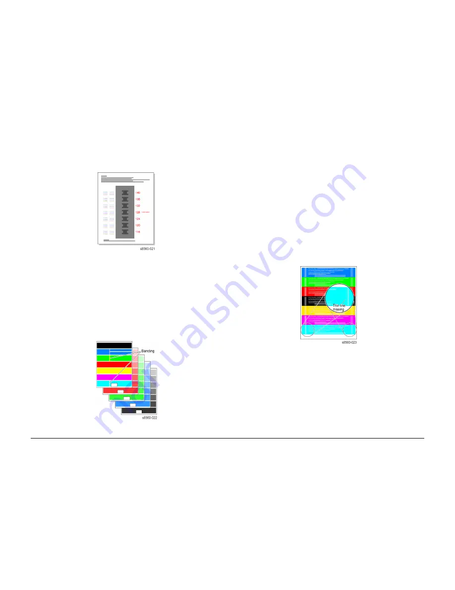
Reverse Text
The print indicates if the printhead is producing properly-sized drops of ink and that the drum
temperature is not too high.
NOTE: This print should be made with the system covers closed and in place. The heat loss
without the covers can hide the “too-hot” thermal problem. Also print the test print in Enhanced
print mode.
Look for: Legibility in the lines of 6-point text, particularly in the primary colors. If the letters are
closed or badly “plugged” with ink, the printhead is laying down too much ink. A good-quality
print shows five vertical parallel lines of different thicknesses on the left and right side of the
print. If the thinnest line is missing, the printhead is outputting too much ink or the drum tem-
perature is too high.
NOTE: Ensure that the system is not in High Resolution/Photo or Standard print mode.
Causes: Check the thermal regulation of the printhead and of the drum. Make sure that the
drum temperature sensor is correctly mounted and in proper, even contact with the drum. If
necessary, remove the sensor and check it for an accumulation of debris at its contact point.
Replace the drum temperature sensor. Ensure the Printhead drive voltage is set to the default
128.
Figure 4 Test Print 4 Reverse Text
Big Bands Hand Feed OHP
This print allows you to evaluate transparency printing. It prints two transparencies from Tray 1:
one with primary color fills and one with secondary color fills and a band of 50% blue.
Look for: Scratching on the print. Uniformity of fill with no scratching. Evaluate the print on an
overhead projector. Some print artifacts visible on the print do not show when projected. Like-
wise, some defects do not show until projected.
Causes: Confirm that you are using the transparency that is supported for this system. Clean
or replace the paper release blade.
Summary of Contents for PHASER 8560MFP
Page 1: ...701P01133 October 2006 Phaser 8560MFP Multifunction Product Service Documentation...
Page 4: ...10 2006 iv Phaser 8510 8560MFP Multifunction Product Initial Issue Introduction...
Page 22: ...10 2006 1 2 Phaser 8510 8560MFP Multifunction Product Initial Issue Service Call Procedures...
Page 28: ...10 2006 2 2 Phaser 8510 8560MFP Multifunction Product Initial Issue Error Messages and Codes...
Page 84: ...10 2006 3 2 Phaser 8510 8560MFP Multifunction Product Initial Issue Image Quality...
Page 116: ...10 2006 4 2 Phaser 8510 8560MFP Multifunction Product Initial Issue Repairs and Adjustments...
Page 194: ...10 2006 5 2 Phaser 8510 8560MFP Multifunction Product Initial Issue Parts List...
Page 204: ...10 2006 6 2 Phaser 8510 8560MFP Multifunction Product Initial Issue Diagnostics...
Page 256: ...10 2006 7 2 Phaser 8510 8560MFP Multifunction Product Initial Issue Wiring Data...
Page 274: ...10 2006 8 2 Phaser 8510 8560MFP Multifunction Product Initial Issue Theory of Operation...


