I
NSTALLATION
P
ROCEDURE
69
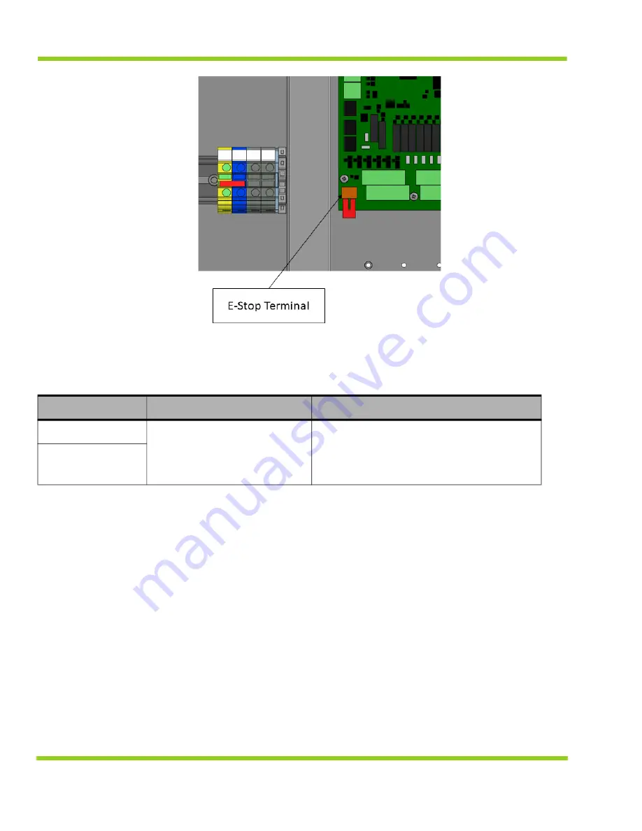
Figure 11-4 PowerGen FPC Expansion Board Emergency Stop Terminal Blocks, Customer Connection
Points
11.3.6 CAN bus Communication Connection
The PowerGen uses the CAN bus communication protocol to communicate to external devices
such as computers. Using the optional CAN to USB cable and Qnergy Lynx software,
communicating to the FPC board is possible. The communication data rate is 125kpps.
Note: Contact Qnergy prior to connecting CAN bus cables to FPC board.
To connect to CAN bus on PowerGen:
• Connect the CAN bus cable to the FCP control circuit board (P12) connector.
11.3.7 PowerGen earth ground connection
The PowerGen requires customer to install an Earth ground connection to the frame of the
PowerGen system. Earth Ground (2/0 – 14 AWG)
Table 11-6 PowerGen FPC Expansion Board Emergency Stop Terminal Block Description
Position
Designation
Wire Gauge
1
Customer contact to
maintain closed circuit to
enable system. Open circuit
disables system
16 - 20
AWG
2
Summary of Contents for PowerGen 5650 Series
Page 1: ...7045 102089 000 June 1 2021 Installation Operation Manual FOR A QUALIFIED INSTALLER...
Page 8: ...iv...
Page 12: ...iv Figure 21 9 ATS Enclosure 179 Figure 21 10 Battery Connection Schematic 181...
Page 28: ...SYSTEM INTRODUCTION 16 Figure 3 6 P ID Diagram...
Page 69: ...QNERGY LYNX SOFTWARE 57 Figure 6 57 FPC FEB QEC Firmware Update...
Page 158: ...MAINTENANCE 146 Figure 17 2 Radiator and Over Flow Tank...
Page 194: ...POWERGEN OPTIONAL FEATURE SETS 182...


