282
Inverter Positioning
Section 5-3
Inverter Positioning with the CP1L
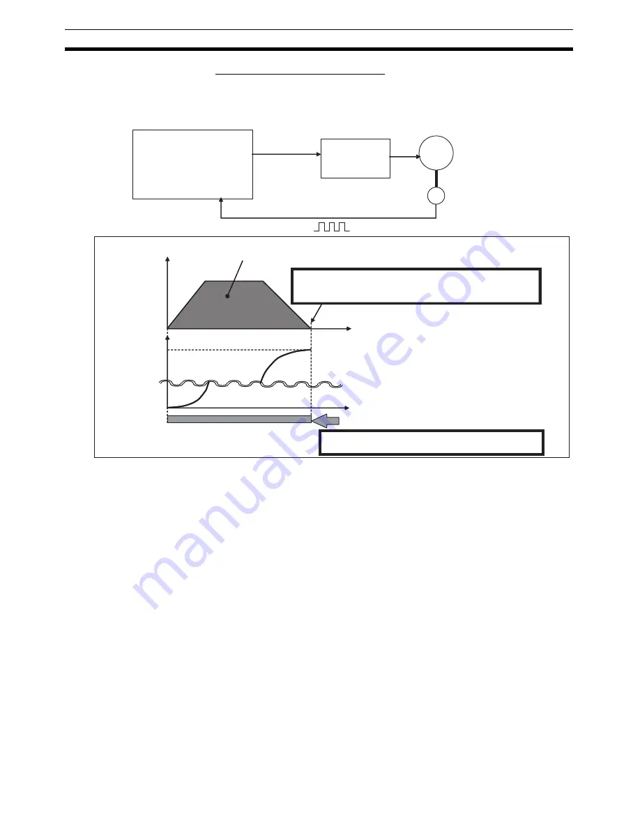
With the CP1L’s inverter positioning function, feedback is constantly read for
the positioning data while controlling the position.
Note
(1) The CP1L’s inverter positioning function is designed to increase position-
ing speed and stopping precision by reading position information and us-
ing a feedback loop with an error counter to switch speeds. It does not
increase the response, stopping precision, or speed change rate of the
inverter and motor. These are characteristics of the inverter and motor.
Refer to user documentation on your inverter and motor for details.
(2) The corresponding pulse output number (0 or 1) cannot be used for the
PULSE WITH VARIABLE DUTY FACTOR instruction (PWM) if inverter
positioning 0 or 1 is used. The high-speed counter of the same number
(0 or 1) is used to input the feedback pulse.
CP1L
Position feedback
Speed command
Inverter
Power
supply
frequency
Inductive motor
Encoder
Feedback pulses
There is no positioning error because the present position and position error
are constantly monitored and corrected.
Frequency
Low-speed operation is not required to prevent
positioning error. Control is simplified because the
low-speed position does not need to be calculated.
Time
Time
Position
Actual/Settings
Command output
Settings/Actual
Positioning is faster because low-speed
operation is not used.
Summary of Contents for CP1L CPU UNIT - 03-2009
Page 1: ...Cat No W462 E1 06 CP1L CPU Unit SYSMAC CP Series CP1L L_0D_ CP1L M_0D_ OPERATION MANUAL...
Page 2: ......
Page 4: ...iv...
Page 10: ...x...
Page 22: ...xxii...
Page 34: ...xxxiv Conformance to EC Directives 6...
Page 70: ...36 Function Blocks Section 1 5...
Page 584: ...550 Trouble Shooting Section 8 7...
Page 627: ...593 Sample Application Section 9 12 Network Settings Network Tab Network Settings Driver Tab...
Page 630: ...596 Sample Application Section 9 12...
Page 654: ...620 Troubleshooting Unit Errors Section 11 4...
Page 662: ...628 Replacing User serviceable Parts Section 12 2...
Page 668: ...634 Standard Models Appendix A...
Page 698: ...664 Auxiliary Area Allocations by Function Appendix C...
Page 746: ...712 Auxiliary Area Allocations by Address Appendix D...
Page 773: ...739 Connections to Serial Communications Option Boards Appendix F Connecting to Unit...
Page 774: ...740 Connections to Serial Communications Option Boards Appendix F...
Page 806: ...772 Index...
Page 808: ...774 Revision History...


