background image

829

Chapter 27

Electrical Specification

User’s Manual U16702EE3V2UD00

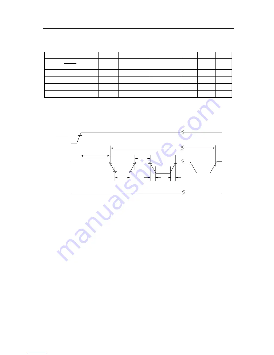
27.10.4  External Flash programmer serial write operation characteristics

Note:

α

 = oscillation stabilization time

Figure 27-17:

Flash EPROM Serial Programming Operation Characteristics

Parameter

Symbol

Conditions

MIN.

TYP.

MAX.

Unit

FLMD0 setup time (from 
release of RESET signal)

t

RFCF

16581/f

X

+

α 

Note

-

-

s

FLMD0 high level width

t

CH

10

-

100

µs

FLMD0 low level width

t

CL

10

-

100

µs

FLMD0 rise time

t

RF

-

-

50

ns

FLMD0 fall time

t

F

-

-

50

ns

t

RFCF

RESET

t

CH

FLMD0

FLMD1

L

t

COUNT

t

CL

t

F

t

R

Downloaded from 

Elcodis.com


electronic components distributor


Summary of Contents for V850E/RS1

Page 1: ...ip Microcontroller with CAN Interface Hardware PD70F3402 PD70F3403 PD70F3403A Document No U16702EE3V2UD00 Date Published April 2006 NEC Electronics Corporation 2006 Printed in Germany Downloaded from...

Page 2: ...static electricity Semiconductor devices must be stored and transported in an anti static container static shielding bag or conductive material All test and measurement tools including work benches a...

Page 3: ...ly To minimize risks of damage to property or injury including death to persons arising from defects in NEC Electronics products customers must incorporate sufficient safety measures in their design s...

Page 4: ...O C Tel 02 2719 2377 NEC Electronics Singapore Pte Ltd 238A Thomson Road 12 08 Novena Square Singapore 307684 Tel 6253 8311 http www sg necel com For further information please contact G05 11 1A Europ...

Page 5: ...tion are used as follows Weight in data notation Left is high order column right is low order column Active low notation xxx pin or signal name is over scored or xxx slash before signal name Memory ma...

Page 6: ...6 User s Manual U16702EE3V2UD00 Downloaded from Elcodis com electronic components distributor...

Page 7: ...ters 70 3 3 Operation Modes 74 3 3 1 Operation modes 74 3 4 Address Space 75 3 4 1 CPU address space 75 3 4 2 Image 76 3 4 3 Wrap around of CPU address space 77 3 4 4 Memory map 78 3 4 5 Memory areas...

Page 8: ...4 6 22 Port block type G SDJ8E 194 4 6 23 Port block type E DWJ4 195 4 6 24 Port block type U SDW11 196 4 6 25 Port block type W SD11 197 4 6 26 Port block type W SD12E 198 4 6 27 Port block type U SD...

Page 9: ...o TPnMD0 000 275 7 5 3 External event counter mode TPnMD2 to TPnMD0 001 278 7 5 4 External trigger pulse mode TPnMD2 to TPnMD0 010 281 7 5 5 One shot pulse mode TPnMD2 to TPnMD0 011 284 7 5 6 PWM mode...

Page 10: ...in standby modes 392 11 6 5 Compare match interrupt in timer trigger mode External trigger mode 393 11 6 6 Timing that makes the A D conversion result undefined 393 11 7 Cautions 395 11 8 How to Read...

Page 11: ...lanation of Queued CSI Functions 476 14 3 1 Transmit Buffer 476 14 3 2 Serial Data Direction Select Function 477 14 3 3 Data Length Select Function 478 14 3 4 Slave Mode 479 14 3 5 Master Mode 479 14...

Page 12: ...message buffer 626 16 8 4 Transition from initialization mode to operation mode 627 16 8 5 Resetting error counter CnERC of CAN module 628 16 9 Message Reception 629 16 9 1 Message reception 629 16 9...

Page 13: ...17 17 5 1 Illegal opcode definition 717 17 5 2 Debug trap 719 17 6 Interrupt Acknowledge Time of CPU 721 17 7 Periods in Which Interrupts Are Not Acknowledged by CPU 722 Chapter 18 Standby Function 72...

Page 14: ...hip debug unit 767 22 1 2 Debug functions 767 22 2 Security Function 770 22 3 Control Register 771 22 4 Operation of On Chip Debug Function 773 22 5 Connection to N Wire Emulator 774 22 5 1 KEL connec...

Page 15: ...power supply current PD70F3403 PD70F3403A 806 27 8 AC Characteristics 807 27 8 1 General condition 807 27 8 2 AC test input waveform 807 27 8 3 Input waveform 808 27 8 4 Output waveform 808 27 8 5 RES...

Page 16: ...16 User s Manual U16702EE3V2UD00 Appendix A Instruction Set List 835 Appendix B Index 843 Appendix C Revision History 849 Downloaded from Elcodis com electronic components distributor...

Page 17: ...Chip Debug Function Is Not Used 88 Figure 3 28 Timing Chart of Transition to Normal Operation Mode 88 Figure 3 29 Timing Chart of Transition to On Chip Debug Mode 89 Figure 3 30 Programmable Peripher...

Page 18: ...wn Resistor Option Register 9 PD9 Format 152 Figure 4 49 External Interrupt Falling Edge Specification Register 9H INTF9H Format 153 Figure 4 50 External Interrupt Rising Edge Specification Register 9...

Page 19: ...10 Bus Read Timing Bus Size 8 bit 227 Figure 5 11 Bus Write Timing Bus Size 16 bit 16 bit Access 228 Figure 5 12 Bus Write Timing Bus Size 8 bit 229 Figure 5 13 Address Wait Timing Bus Size 16 bit 230...

Page 20: ...ing in Free Running Mode TPnCCS1 1 TPnCCS0 0 TPnOE0 1 TPnOE1 1 TPnOL0 0 TPnOL1 0 295 Figure 7 31 Basic Operation Timing in Free Running Mode TPnCCS1 0 TPnCCS0 1 TPnOE0 1 TPnOE1 1 TPnOL0 0 TPnOL1 0 296...

Page 21: ...ADSCM0L Format 1 2 375 Figure 11 6 AD Converter Mode Register 1H ADSCM1H Format 377 Figure 11 7 AD Converter Extended Mode Register ADVMS0 378 Figure 11 8 AD Converter External Trigger Selection Regi...

Page 22: ...uous Reception Flow Master 458 Figure 13 23 Continuous Transmission Reception Flow Master 459 Figure 13 24 Continuous Reception Flow Slave 460 Figure 13 25 Prescaler Mode Register 0 PRSM0 Format 461 F...

Page 23: ...ode Example 1 Channel 522 Figure 15 14 Single Transfer Mode Example 3 Channels 522 Figure 15 15 Fixed Channel Transfer Example 2 Channels 523 Figure 15 16 Fixed Channel Transfer Mode Example 3 Channel...

Page 24: ...Module Terminal Connection in Receive Only Mode 648 Figure 16 55 CAN Module Terminal Connection in Self Test Mode 650 Figure 16 56 Timing Diagram of Capture Signal TSOUT 651 Figure 16 57 Initializati...

Page 25: ...Processing 718 Figure 17 29 Restore Processing from Exception Trap 718 Figure 17 30 Debug Trap Processing Format 719 Figure 17 31 Processing Format of Restoration from Debug Trap 720 Figure 17 32 Pipe...

Page 26: ...ion Function 788 Figure 25 1 Block Diagram of Clock Monitor 789 Figure 25 2 Clock Monitor Mode Register CLM Format 790 Figure 25 3 When Oscillation of Main Clock Is Stopped 791 Figure 25 4 Operation i...

Page 27: ...n List 256 Table 7 3 Tuned Operation Mode of Timer 299 Table 7 4 Timer Modes Usable in Tuned Operation Mode 299 Table 7 5 Timer Output Functions 300 Table 8 1 TMQ Configuration 304 Table 8 2 TMQ Pin L...

Page 28: ...ication 709 Table 17 5 Valid Edge Specification 710 Table 17 6 Valid Edge Specification 711 Table 17 7 Valid Edge Specification 712 Table 18 1 Standby Modes 723 Table 18 2 Operation After Releasing HA...

Page 29: ...nstructions corresponding to high level languages which makes a program compact Furthermore since interrupt response time including processing by the on chip interrupt controller also is fast this CPU...

Page 30: ...lock generator fXX fX fX 4 to 8 MHz direct mode fXX fPLL 24 MHz 32 MHz PLL mode for PD70F3402 fXX fPLL 24 MHz 32 MHz 40 MHz PLL mode for PD70F3403 and PD70F34033A Power supply voltage range 4 0 V to 5...

Page 31: ...est signals Exceptions Software exceptions 32 sources Exception trap 2 sources illegal opcode exception DMA transfer function 6 independent channels On chip power on reset On chip low voltage indicato...

Page 32: ...for other applications where a combination of sophisticated peripheral functions with CAN network support is required like Body Electronics Applica tion 1 4 Ordering Information Part No Package Qualit...

Page 33: ...D1 P36 CTXD1 P37 TIP00 TOP00 INTP1 CS312 P38 TIP01 TOP01 V DD1 REGC1 V SS1 P50 TIQ01 TOQ01 P51 TIQ02 TOQ02 P52 TIQ03 TOQ03 P53 TIQ00 TOQ00 P54 SI30 P55 SO30 P90 TIQ11 TOQ11 SCK30 P91 TIQ12 TOQ12 CS300...

Page 34: ...CS1Note Chip select SIB0 to SIB1 Serial input CS300 to CS303 Serial Chip Select SO30 SO31 Serial output CS310 to CS313 Serial Chip Select SOB0 to SOB1 Serial output DCK Debug clock TIP00 TIP01 Timer...

Page 35: ...1 AD0 to AD15 Ports CG RG Clock monitor POC LVI System control PLL1 PLL0 PCM0 to PCM3 PCT0 PCT1 PCT4 PCT6 PCS0 PCS1 PDL0 to PDL13 P90 to P915 P70 to P715 P50 to P55 P40 to P42 P30 to P38 P10 to P12 P0...

Page 36: ...Kbytes The PD70F3403 and PD70F3403A have an on chip flash memory of 256 Kbytes The 128 KB or 256 KB flash memory are mapped to the address spaces from 0000000H to 001FFFFH or 0000000H to 003FFFFH resp...

Page 37: ...ferred via the SOBm pins SIBm pins and SCKBm pins m 0 1 In the case of CSI3 data is transferred via the SO3m pins SIm pins and SCK3m pins m 0 1 A dedicated baud rate generator is provided on chip for...

Page 38: ...xternal interrupt serial interface I O timer I O P4 3 bit I O Serial interface I O P5 6 bit I O Timer I O Serial interface I O P7 16 bit I O A D converter analog input P9 16 bit I O Serial interface I...

Page 39: ...t 4 Port 5 Port 9 NMI RESET and Regulator for Internal circuit CPU RAM and FLASH memory Table 2 2 Port Pins 1 2 Pin Name I O Function Alternate Function P00 I O Port 0 7 bit I O port Input output can...

Page 40: ...1 DDI P98 SOB1 DCK P99 SCKB1 DMS P910 CS301 DDO P911 DRST P912 TIP21 TOP21 CS302 P913 TIP20 TOP20 INTP4 PCL P914 TIP10 TOP10 INTP5 AD14 Note P915 TIP11 TOP11 INTP6 AD15 Note PCM0 I O Port CM 4 bit I O...

Page 41: ...lock input TMP21 P912 TOP21 CS302 TIP30 External event clock input TMP30 P11 TOP31 TIP31 External event clock input TMP31 P12 TOP30 ADTRG TOP00 Output Timer output TMP00 P37 TIP00 INTP1 CS312 TOP01 Ti...

Page 42: ...ut CSI30 P91 TIQ12 TOQ12 P96 TXDA1 CS301 Serial chip select output CSI30 P92 TIQ13 TOQ13 CS302 Serial chip select output CSI30 P93 TIQ10 TOQ10 CS303 Serial chip select output CSI30 P94 ASCKA1 CS310 Se...

Page 43: ...Output Internal system clock output PCM1 PCL Output Clock output for trimming of X1 input clock subsystem clock P913 TIP20 TOP20 INTP4 REGC0 Connection of regulator output stabilization capacitance RE...

Page 44: ...Held The state during the immediately preceding external bus cycle is held L Low level output H High level output Input without sampling not acknowledged Table 2 4 Pin Operation States in Various Mod...

Page 45: ...p pull down resistor option register 0 PU0 PD0 a Port mode P00 to P06 can be set to input or output in 1 bit units using port mode register 0 PM0 b Control mode P00 to P06 can be set to control modes...

Page 46: ...ull up pull down resistor option register 1 PU1 PD1 a Port mode P10 and P12 can be set to input or output in 1 bit units using port mode register 1 PM1 b Control mode P10 to P12 can be set to control...

Page 47: ...er 3 PMC3 port mode function register 3 PFC3 and port mode function expand register 3 PFCE3 RXDA0 receive data Input These are the serial receive transmit input pins for UARTA0 TXDA0 transmit data Out...

Page 48: ...or use in 1 bit units using pull up pull down resistor option register 4 PU4 PD4 a Port mode P40 to P42 can be set to input or output in 1 bit units using port mode register 4 PM4 b Control mode P40 t...

Page 49: ...5 PU5 PD5 a Port mode P50 to P55 can be set to input or output in 1 bit units using port mode register 5 PM5 b Control mode P50 to P55 can be set to control modes in 1 bit units using port mode contr...

Page 50: ...on verter in the control mode However they cannot be switched between input port and analog out put pin a Port mode P70 to P715 can be set to input or output in 1 bit units using port mode register 7...

Page 51: ...ster 9 PMC9 port mode function register 9 PFC9 and port mode function expand register 9 PFCE9 SIB1 serial input input These are the serial receive data input pins for CSIB1 SOB1 serial output output T...

Page 52: ...nd control bus are in high impedance while this signal is active HLDRQ hold request Input This is an input pin by which an external device requests the V850E RS1 to release the address bus data bus an...

Page 53: ...input or output in 1 bit units using port mode register CS PMCS b Control mode PCS0 and PCS1 can be set to control modes in 1 bit units using port mode control register CS PMCCS CS0 CS1 chip select i...

Page 54: ...ol modes in 1 bit units using port mode control reg ister CT PMCCT WR0 write strobe low level data Output This is the write strobe signal output pin for the lower data of the external 16 bit data bus...

Page 55: ...FLMD1 pin a Port mode PDL0 to PDL13 can be set to input or output in 1 bit units with the port DL mode register PMDL b Control mode PDL0 to PDL13 can be set to control modes in 1 bit units using port...

Page 56: ...cel a standby mode STOP 14 X1 X2 crystal for main clock These pins are used to connect the resonator that generates the system clock 15 AVSS analog VSS This is the ground pin for the A D converter and...

Page 57: ...stor P11 TIP31 TOP31 P12 TIP30 TOP30 ADTRG P30 TXDA0 ASCKA0 5 AM Connect it to VDD1 or VSS1 through independent resistor P31 RXDA0 INTP7 P32 ASCKA0 TXDA0 CS310 P33 CTXD0 P34 CRXD0 P35 CRXD1 P36 CTXD1...

Page 58: ...DRST 5 AM P912 TIP21 TOP21 CS302 5 AM P913 TIP20 TOP20 INTP4 PCL 5 AM P914 TIP10 TOP10 INTP5 AD14 5 AM Connect it to BVDD or BVSS through independent resistor P915 TIP11 TOP11 INTP6 AD15 5 AM PCM0 WAI...

Page 59: ...MD0 See 21 6 1 FLMD0 pin on page 756 RESET 2 External system reset input VDD0 Power supply pin for PLL VSS0 Ground potential pin for PLL X1 Connection of resonator for main clock X2 VDD1 Power supply...

Page 60: ...disable Input enable VDD0 P ch VDD0 P ch IN OUT N ch VSS0 Type 5 AE Type 5 AM Type 11 G IN Type 2 pull up enable pull down enable data output disable input enable VDD P ch VDD P ch IN OUT N ch N ch d...

Page 61: ...sters 32 bits 32 registers Internal 32 bit architecture 5 stage pipeline control Hardware interlock on register flag hazards Instruction set Upwardly compatible with V850 CPU Multiplication division i...

Page 62: ...tem register set r0 r1 r2 r3 r4 r5 r6 r7 r8 r9 r10 r11 r12 r13 r14 r15 r16 r17 r18 r19 r20 r21 r22 r23 r24 r25 r26 r27 r28 r29 r30 r31 Zero register Assembler reserved register Stack pointer SP Global...

Page 63: ...am counter holds the instruction address during program execution The lower 32 bits of this register are valid Bits 31 to 26 are fixed to 0 A carry from bit 25 to 26 is ignored even if it occurs Bit 0...

Page 64: ...e by the RETI instruction after interrupt servicing this is because bit 0 of the PC is fixed to 0 Set an even value to EIPC FEPC and CTPC bit 0 0 Remark Can be accessed Access prohibited Table 3 2 Sys...

Page 65: ...software exception or a maskable interrupt occurs The current contents of the PSW are saved to EIPSW Because only one set of interrupt status saving registers is available the contents of these regis...

Page 66: ...fixed to 0 Figure 3 4 NMI Status Saving Registers FEPC and FEPSW Format 3 Interrupt source register ECR The interrupt source register ECR holds the source of an exception or interrupt if an exception...

Page 67: ...n be acknowledged 0 Interrupt enabled 1 Interrupt disabled 4 SATNote Indicates that the result of a saturation operation has overflowed and is saturated Because this is a cumulative flag it is set to...

Page 68: ...or future function expansion Figure 3 7 CALLT Execution Status Saving Registers CTPC and CTPSW Format The values of CTPC and CTPSW are restored to PC and PSW during execution of the CTRET instruction...

Page 69: ...xed to 0 for future function expansion Figure 3 8 Exception Debug Trap Status Saving Registers DBPC and DBPSW Format The values of DBPC and DBPSW are restored to PC and PSW during execution of the DBR...

Page 70: ...Clock monitor mode register CLM Reset control flag register RESF Low voltage detection register LVIM Internal RAM data status register RAMS On chip debug mode setting register OCDM In addition a comm...

Page 71: ...NOP Dummy instruction 10 SET1 0 DCHCn r0 Enable DMA operation n 0 to 5 next instruction There is no special sequence to read a special register Cautions 1 When a store instruction is executed to store...

Page 72: ...n with store instruction execution by CPU only not with DMA trans fer If an illegal store operation to a special register takes place it can be checked by the PERR flag of the system status register S...

Page 73: ...fter writing data to the PRCMD register if 4 in 3 4 8 1 Setting special register is not the setting of a special register b Clear condition PRERR 0 When 0 is written to the PRERR flag of the SYS regis...

Page 74: ...H PMCDL PMCCM PMCCS and PMCCT registers to the control mode using instructions an external device can be connected to the exter nal memory area 2 Flash memory programming mode In this mode the interna...

Page 75: ...f linear address space program space for instruction addressing Note however that both the program and data spaces have areas that are prohibited from being used For details refer to Figure 3 13 Image...

Page 76: ...ur 64 MB physical address spaces This means that the same 64 MB physical address space is accessed regardless of the values of bits 31 to 26 Figure 3 13 Image on Address Space Program space Internal R...

Page 77: ...KB area of addresses 03FFF000H to 03FFFFFFH is a peripheral I O area instructions cannot be fetched from this area Therefore do not execute an operation in which the result of a branch address calcula...

Page 78: ...ibited Internal ROM area Note 1 MB External memory area 1 MB External memory area 2 MB Internal RAM area 60 KB Internal peripheral I O area 4 KB Use prohibited Memory block 0 2 MB Memory block 1 2 MB...

Page 79: ...60 KB Programmable peripheral I O area or use prohibited program fetch prohibited area Use prohibited program fetch prohibited area External memory area 12 MB External memory area 1 MB Internal ROM a...

Page 80: ...FH 03FF FFFFH PD70F3402 Internal peripheral I O area 4 KB Internal RAM area 10 KB aFCAN area 12 KB Internal ROM area 256 KB 0020 0000H 001F FFFFH 0004 0000H 0003 FFFFH 0000 0000H 0040 0000H 003F FFFFH...

Page 81: ...response time by fixing handler addresses corresponding to interrupts exceptions A collection of these handler addresses is called an interrupt exception table which is mapped to the internal ROM area...

Page 82: ...es as physical internal RAM Addresses 3FFC800H to 3FFEFFFH Figure 3 20 Internal RAM Area 10 KB b PD70F3403 and PD70F3403A 16 KB are provided in the following addresses as physical internal RAM Address...

Page 83: ...Cautions 1 When a register is accessed in word units a word area is accessed twice in half word units in the order of lower area and higher area with the lower 2 bits of the address ignored 2 If a re...

Page 84: ...unconditionally corresponds to the memory map To use the internal RAM area as the program space access addresses 3FFC000H to 3FFEFFFH 2 Data space With the V850E RS1 there are sixty four 64 MB address...

Page 85: ...al RAM Internal ROM External memory Use prohibited External memory Use prohibited Internal RAM Internal peripheral I ONote Program space 64 MB Internal ROM Internal ROM FFFF FFFFH FFFF F000H FFFF EFFF...

Page 86: ...The system wait control register VSWC controls wait of bus access to the internal peripheral I O registers Three clocks are required to access an internal peripheral I O register without a wait cycle...

Page 87: ...can be read and written in 8 bit or 1 bit units Figure 3 26 On Chip Debug Mode Register OCDM Format Notes 1 On input to RESET pin external reset OCDM0 1 On power on reset OCDM0 0 On occurrence of inte...

Page 88: ...Maintain low level High level I O is possible after clearing of OCDM0 bit Clearing of OCDM0 bit Reset release RESET OCDM0 P911 DRST RESET external reset input POC internal reset OCDM0 DRST on chip de...

Page 89: ...data may be transferred If there is a possibility of a conflict the number of cycles for accessing the CPU changes when the peripheral hardware is accessed so that correct data is transferred As a res...

Page 90: ...bit timer event counter Q TMQ m 0 1 TQmCNT Read 1 or 2 TQmCCR0 Write 1st access No wait Continuous write 3 or 4 Read 1 or 2 TQmCCR1 Write 1st access No wait Continuous write 3 or 4 Read 1 or 2 TQmCCR...

Page 91: ...MIN Note fXX fCANMODE 2 1 1 2 j MAX Note Read fXX fCANMODE 3 1 1 2 j MIN Note fXX fCANMODE 4 1 1 2 j MAX Note CnLIPT CnLOPT Read fXX fCANMODE 3 1 1 2 j MIN Note fXX fCANMODE 4 1 1 2 j MAX Note CnMDATA...

Page 92: ...le if BPC 0x8FFB the programmable area is set to 3FEC000H Figure 3 30 Programmable Peripheral I O Control Register BPC Format Caution When using the CAN controller PA15 1 be sure to set 8FFBH to this...

Page 93: ...T mode control register PMCCT R W 00H FFFFF04CH Port CM mode control register PMCCM R W 00H FFFFF064H Peripheral area selection control register BPC R W 0000H FFFFF066H Bus size configuration register...

Page 94: ...terrupt control register TP3OVIC R W 47H FFFFF140H Interrupt control register TP3CCIC0 R W 47H FFFFF142H Interrupt control register TP3CCIC1 R W 47H FFFFF144H Interrupt control register TM0EQIC0 R W 4...

Page 95: ...ADSCM0 R W 0000H FFFFF200H A D converter scan mode register 0L ADSCM0L R W 00H FFFFF201H A D converter scan mode register 0H ADSCM0H R W 00H FFFFF203H A D converter scan mode register 1H ADSCM1H R W 0...

Page 96: ...9 P9 R W undefined FFFFF412H Port 9L P9L R W undefined FFFFF413H Port 9H P9H R W undefined FFFFF420H Port 0 mode register PM0 R W FFH FFFFF422H Port 1 mode register PM1 R W FFH FFFFF426H Port 3 mode r...

Page 97: ...FF543H TMQ0 timer specific I O control register 1 TQ0IOC1 R W 00H FFFFF544H TMQ0 timer specific I O control register 2 TQ0IOC2 R W 00H FFFFF545H TMQ0 timer option register TQ0OPT0 R W 00H FFFFF546H TM...

Page 98: ...r specific I O control register 2 TP3IOC2 R W 00H FFFFF5C5H TMP3 timer option register TP3OPT0 R W 00H FFFFF5C6H TMP3 capture compare register 0 TP3CCR0 R W 0000H FFFFF5C8H TMP3 capture compare regist...

Page 99: ...R W 00H FFFFF86CH Clock selection register 3 OCKS3 R W 00H FFFFF870H Clock monitor mode register CLM R W 00H FFFFF87AH Port Function Swap control register PSWAP R W 00H FFFFF888H Reset status flag reg...

Page 100: ...r P21NFC R W 00H FFFFFB18H TIP30 noise filter circuit control register P30NFC R W 00H FFFFFB1CH TIP31 noise filter circuit control register P31NFC R W 00H FFFFFB50H TIQ00 noise filter circuit control...

Page 101: ...PD4 R W 00H FFFFFCAAH Pull down resistor option register 5 PD5 R W 00H FFFFFCB2H Pull down resistor option register 9 PD9 R W 0000H FFFFFCB2H Pull down resistor option register 9L PD9L R W 00H FFFFFCB...

Page 102: ...SFCS1 R W FFFFH FFFFFD64H CSI31 chip select FIFO buffer L SFCS1L R W FFH FFFFFD65H CSI31 chip select FIFO buffer H SFCS1H R W FFH FFFFFD66H CSI31 transmit data FIFO buffer SFDB1 R W 0000H FFFFFD66H C...

Page 103: ...ource address register H DMSA2H R W FFFFFE24H MDMA ch2 destination address register DMDA2 R W FFFFFE24H MDMA ch2 destination address register L DMDA2L R W FFFFFE26H MDMA ch2 destination address regist...

Page 104: ...ddress register DMDA5 R W FFFFFE48H MDMA ch5 destination address register L DMDA5L R W FFFFFE4AH MDMA ch5 destination address register H DMDA5H R W FFFFFE4CH MDMA ch5 transfer count register DMBC5 R W...

Page 105: ...S1 features a total of 84 I O ports consisting of the ports 0 1 3 4 5 7 9 CM CS CT and DL The port configuration is shown below Figure 4 1 Port Configuration Diagram Port 1 P10 P12 Port 3 P30 P38 Port...

Page 106: ...ET pins have no Port function Table 4 1 I O Buffer Power Supplies for Pins Power Supply Corresponding Pin AVREF0 Port 7 BVDD1 Port CM Port CS port CT port DL VDD1 Port 0 Port 1 Port 3 Port 4 Port 5 Po...

Page 107: ...EGC0 11 VSS0 12 X1 13 X2 14 RESET RESET 15 P00 SI31 P00 SI31 x x x 16 P01 SO31 P01 SO31 x x x 17 P02 SCK31 P02 SCK31 x x x 18 P03 CS310 P03 CS310 No Func x x x 19 P04 CS311 P04 CS311 x x x 20 P05 CS31...

Page 108: ...CS301 No Func TOQ13 TIQ13 46 P93 TIQ10 TOQ10 CS302 P93 CS302 No Func TOQ10 TIQ10 47 P94 ASCKA1 CS303 P94 CS303 ASCKA1 x x 48 P95 RXDA1 SCK30 P95 RXDA1 SCK30 RXDA1 x x 49 P96 TXDA1 CS300 P96 TXDA1 CS30...

Page 109: ...x x 76 PDL5 AD5 FLMD1 PDL5 AD5 x x x FLMD1 77 PDL6 AD6 PDL6 AD6 x x x 78 PDL7 AD7 PDL7 AD7 x x x 79 PDL8 AD8 PDL8 AD8 x x x 80 PDL9 AD9 PDL9 AD9 x x x 81 PDL10 AD10 PDL10 AD10 x x x 82 PDL11 AD11 PDL1...

Page 110: ...4 5 7H 7L 9 CM CS CT DL Port function control register PFCn n 0 1 3 5 9 Port function control expansion register PFCEn n 3 5 9 Pull up resistor option register PUn n 0 1 3 4 5 9 CM CS CT Pull down res...

Page 111: ...ol bit is shown in Table 4 2 Control Register Setting on page 107 This is an 8 bit register used to specify the input mode output mode This register can be read and written in 8 bit or 1 bit units Fig...

Page 112: ...0 See Table 4 8 Port Type on page 170 for alternate functions of Port 0 2 Registers a Port register 0 P0 Port register 0 P0 is an 8 bit register that controls pin level read output level write It can...

Page 113: ...fter reset PM0 1 PM06 PM05 PM04 PM03 PM02 PM01 PM00 FFFFF420H FFH R W R W R W R W R W R W R W R W R W PM0n I O mode control n 0 to 6 0 Output mode 1 Input mode Symbol 7 6 5 4 3 2 1 0 Address After res...

Page 114: ...n 0 I O port 1 SCK31 Serial clock input output for CSI31 PMC01 P01 pin operation mode specification 0 I O port 1 SO31 Serial output for CSI31 PMC00 P00 pin operation mode specification 0 I O port 1 SI...

Page 115: ...esistor This register can be read and written in 8 bit or 1 bit units Figure 4 8 Pull down Resistor Option Register 0 PD0 Format Symbol 7 6 5 4 3 2 1 0 Address After reset PU0 0 PU06 PU05 PU04 PU03 PU...

Page 116: ...port function edge detection may occur Therefore set the port mode after set ting INTF0n INTR0n bit 0 2 An on chip circuit for eliminating noise through analog delay is provided for external interrupt...

Page 117: ...0n INTR0n bit 0 2 An on chip circuit for eliminating noise through analog delay is provided for external interrupt input Figure 4 10 External Interrupt Rising Edge Specification Register 0 INTR0 Forma...

Page 118: ...ister 0 INTR1 See Table 4 8 Port Type on page 170 for alternate functions 2 Registers a Port register 1 P1 Port register 1 P1 is an 8 bit register that controls pin level read output level write It ca...

Page 119: ...mbol 7 6 5 4 3 2 1 0 Address After reset PM1 1 1 1 1 1 PM12 PM11 PM10 FFFFF422H FFH R W R W R W R W R W R W R W R W R W PM1n I O mode control n 0 to 2 0 Output mode 1 Input mode Symbol 7 6 5 4 3 2 1 0...

Page 120: ...igure 4 15 Port Function Control Extended Register 1 PFCE1 Format Remark For details on control mode specification refer to 4 3 4 2 f P1 pin control mode set tings f P1 pin control mode settings Symbo...

Page 121: ...l down resistor This register can be read and written in 8 bit or 1 bit units Figure 4 17 Pull down Resistor Option Register 1 PD1 Format Symbol 7 6 5 4 3 2 1 0 Address After reset PU1 0 0 0 0 0 PU12...

Page 122: ...e port function edge detection may occur Therefore set the port mode after set ting INTF1n INTR1n bit 0 2 An on chip circuit for eliminating noise through analog delay is provided for external interru...

Page 123: ...er set ting INTF10 INTR10 bit 0 2 An on chip circuit for eliminating noise through analog delay is provided for external interrupt input Figure 4 19 External Interrupt Rising Edge Specification Regist...

Page 124: ...ecifiable in 1 bit units by port function control register 3 PFC3 PFCE3 On chip pull up resistor specifiable in 1 bit units by pull up resistor option register 3 PU3 On chip pull down resistor specifi...

Page 125: ...rite the data written to P3 is written This does not affect the input pins Output mode When port 3 P3 is read the value of P3 is read During write the value is written to P3 and the written value is i...

Page 126: ...8 bits as the PM3L register PM3 can be read and written in 8 bit and 1 bit units Figure 4 21 Port Mode Register 3 PM3 Format Symbol 15 14 13 12 11 10 9 8 Address After reset PM3H 1 1 1 1 1 1 1 PM38 FF...

Page 127: ...R W R W R W R W Symbol 7 6 5 4 3 2 1 0 Address After reset PMC3L PMC37 PMC36 PMC35 PMC34 PMC33 PMC32 PMC31 PMC30 FFFFF446H 0000H R W R W R W R W R W R W R W R W R W PMC38 P38 pin operation mode specif...

Page 128: ...put for aFCAN0 PMC32 P32 pin operation mode specification 0 I O port 1 ASCKA0 TXDA0 CS312 Serial clock input for UARTA0 Serial output for UARTA0 Chip select0 for CSI31 PMC31 P31 pin operation mode spe...

Page 129: ...ngs f P3 pin control mode settings Symbol 7 6 5 4 3 2 1 0 Address After reset PFCE3 PFCE37 0 0 0 0 0 0 0 FFFFF706H 0000H R W R W R W R W R W R W R W R W R W PFC38 P38 Pin Control Mode Specification 0...

Page 130: ...her 8 bits of the PD3 register as the PD3H register and the lower 8 bits as the PD3L register PD3 can be read and written in 8 bit and 1 bit units Figure 4 26 Pull down Resistor Option Register 3 PD3...

Page 131: ...function to the port function edge detection may occur Therefore set the port mode after set ting INTF3 INTR3 bit 0 2 An on chip circuit for eliminating noise through analog delay is provided for ext...

Page 132: ...rt mode after set ting INTF3 INTR3 bit 0 2 An on chip circuit for eliminating noise through analog delay is provided for external interrupt input Figure 4 28 External Interrupt Rising Edge Specificati...

Page 133: ...register 4 P4 is an 8 bit register that controls pin level read output level write It can be read and written in 8 bit or 1 bit units Figure 4 29 Port Register 4 P4 Format Remarks 1 Input mode When po...

Page 134: ...Format Symbol 7 6 5 4 3 2 1 0 Address After reset PM4 1 1 1 1 1 PM42 PM41 PM40 FFFFF428H FFH R W R W R W R W R W R W R W R W R W PM4n I O mode control n 0 to 2 0 Output mode 1 Input mode Symbol 7 6 5...

Page 135: ...l down resistor This register can be read and written in 8 bit or 1 bit units Figure 4 33 Pull down Resistor Option Register 4 PD4 Format Symbol 7 6 5 4 3 2 1 0 Address After reset PU4 0 0 0 0 0 PU42...

Page 136: ...P5 Port register 5 P5 is an 8 bit register that controls pin level read output level write It can be read and written in 8 bit or 1 bit units Figure 4 34 Port Register 5 P5 Format Remarks 1 Input mod...

Page 137: ...Format 1 2 Symbol 7 6 5 4 3 2 1 0 Address After reset PM5 1 1 PM55 PM54 PM53 PM52 PM51 PM50 FFFFF42AH FFH R W R W R W R W R W R W R W R W R W PM5n I O mode control n 0 to 5 0 Output mode 1 Input mode...

Page 138: ...For details on control mode specification refer to e P5 pin control mode settings PMC52 P52 pin operation mode specification 0 I O port 1 TIQ03 TOQ03 TMQ0 input3 TMQ0 output3 PMC51 P51 pin operation...

Page 139: ...put0 1 TOQ00 output TMQ0 output0 PFC52 P52 Pin Control Mode Specification 0 TIQ03 input TMQ0 input3 1 TOQ03 output TMQ0 output3 PFC51 P51 Pin Control Mode Specification 0 TIQ02 input TMQ0 input2 1 TOQ...

Page 140: ...gister can be read and written in 8 bit or 1 bit units Figure 4 39 Pull down Resistor Option Register 5 PD5 Format Symbol 7 6 5 4 3 2 1 0 Address After reset PD5 0 0 PD55 PD54 PD53 PD52 PD51 PD50 FFFF...

Page 141: ...t 7H P7H and port 7L P7L are read the pin levels at this are read During write the data written to P7H and P7L are written This does not affect the input pins Output mode When port 7H P7H and port 7L...

Page 142: ...PM7H PM7L Format Caution When using P70 to P715 as alternate functions ANI0 to ANI15 set PM7H register and PM7L register FFH Symbol 7 6 5 4 3 2 1 0 Address After reset PM7H PM715 PM714 PM713 PM712 PM...

Page 143: ...by port function control register 9 PFC9 PFCE9 On chip pull up resistor specifiable in 1 bit units by pull up resistor option register 9 PU9 On chip pull down resistor specifiable in 1 bit units by p...

Page 144: ...written to P9 is written This does not affect the input pins Output mode When port 9 P9 is read the value of P9 is read During write the value is written to P9 and the written value is immediately ou...

Page 145: ...nd the lower 8 bits as the PMC9L register PMC9 can be read and written in 8 bit and 1 bit units Figure 4 44 Port Mode Control Register 9 PMC9 Format 1 3 Symbol 15 14 13 12 11 10 9 8 Address After rese...

Page 146: ...MP2 input0 TMP2 output0 External interrupt input4 Programmable clock output PMC912 P912 pin operation mode specification 0 I O port 1 TIP21 TOP21 CS302 TMP2 input1 TMP2 output1 Chip select2 output for...

Page 147: ...SCKA1 CS303 Serial clock input for UARTA1 Chip select3 for CSI30 PMC93 P93 pin operation mode specification 0 I O port 1 TIQ10 TOQ10 CS302 TMQ1 input0 TMQ1 output0 Chip select2 for CSI30 PMC92 P92 pin...

Page 148: ...e higher 8 bits of the PFCE9 register as the PFCE9H register and the lower 8 bits as the PFCE9L register PFCE9 can be read and written in 8 bit and 1 bit units Figure 4 46 Port Function Control Expans...

Page 149: ...TOP10 1 0 TIP10 1 1 AD14Note PFCE913 PFC913 P913 Pin Control Mode Specification 0 0 INTP4 0 1 TOP20 1 0 TIP20 1 1 PCL PFCE912 PFC912 P912 Pin Control Mode Specification 0 0 CS302 0 1 TOP21 1 0 TIP21 1...

Page 150: ...tion 0 0 CS302 0 1 TOQ10 1 0 TIQ10 1 1 Setting prohibited PFCE92 PFC92 P92 Pin Control Mode Specification 0 0 CS301 0 1 TOQ13 1 0 TIQ13 1 1 Setting prohibited PFCE91 PFC91 P91 Pin Control Mode Specifi...

Page 151: ...egister PU9 can be read and written in 8 bit and 1 bit units Figure 4 47 Pull up Resistor Option Register 9 PU9 Format Symbol 15 14 13 12 11 10 9 8 Address After reset PU9H PU915 PU914 PU913 PU912 0 P...

Page 152: ...Register 9 PD9 Format Note 0 Default While OCDM 01H the built in pull down function is enabled for P911 but this state is not indicated in bit PD911 at that time Refer to Chapter 22 On Chip Debug Func...

Page 153: ...function edge detection may occur Therefore set the port mode after set ting INTF9n INTR9n bit 0 2 An on chip circuit for eliminating noise through analog delay is provided for external interrupt inpu...

Page 154: ...on chip circuit for eliminating noise through analog delay is provided for external interrupt input Figure 4 50 External Interrupt Rising Edge Specification Register 9H INTR9H Format Remark For detail...

Page 155: ...d output level write It can be read and written in 8 bit or 1 bit units Figure 4 51 Port Register CM PCM Format Note PCM4 PCM5 please set 0 any time Remarks 1 Input mode When port CM PCM is read the p...

Page 156: ...d and written in 8 bit or 1 bit units Figure 4 52 Port Mode Register CM PMCM Format Note PMCM4 PMCM5 please set 0 any time Symbol 7 6 5 4 3 2 1 0 Address After reset PMCM 1 1 0Note 0Note PMCM3 PMCM2 P...

Page 157: ...4 3 2 1 0 Address After reset PMCCM 0 0 0Note 0Note PMCCM3 PMCCM2 PMCCM1 PMCCM0 FFFFF04CH 00H R W R W R W R W R W R W R W R W R W PMCCM3 PCM3 pin operation mode specification 0 I O port 1 HLDRQ input...

Page 158: ...resistor This register can be read and written in 8 bit or 1 bit units Figure 4 55 Pull down Resistor Option Register CM PDCM Format Symbol 7 6 5 4 3 2 1 0 Address After reset PUCM 0 0 0 0 PUCM3 PUCM2...

Page 159: ...put level write It can be read and written in 8 bit or 1 bit units Figure 4 56 Port Register CS PCS Format Note PCS7 to PCS2 please set 0 any time Remarks 1 Input mode When port CS PCS is read the pin...

Page 160: ...3403 and PD70F3403A Figure 4 58 Port Mode Control Register CS PMCCS Format Note PMCCS7 to PMCCS2 please set 0 any time Symbol 7 6 5 4 3 2 1 0 Address After reset PMCS 0Note 0Note 0Note 0Note 0Note 0No...

Page 161: ...pull down resistor This register can be read and written in 8 bit or 1 bit units Figure 4 60 Pull down Resistor Option Register CS PDCS Format Symbol 7 6 5 4 3 2 1 0 Address After reset PUCS 0 0 0 0...

Page 162: ...level write It can be read and written in 8 bit or 1 bit units Figure 4 61 Port Register CT PCT Format Note PCT7 PCT5 PCT3 PCT2 please set 0 any time Remarks 1 Input mode When port CT PCT is read the...

Page 163: ...en in 8 bit or 1 bit units Figure 4 62 Port Mode Register CT PMCT Format Note PMCT7 PMCT5 PMCT3 PMCT2 please set 0 any time Symbol 7 6 5 4 3 2 1 0 Address After reset PMCT 0Note PMCT6 0Note PMCT4 0Not...

Page 164: ...time Symbol 7 6 5 4 3 2 1 0 Address After reset PMCCT 0Note PMCCT6 0Note PMCCT4 0Note 0Note PMCCT1 PMCCT0 FFFFF04AH 00H R W R W R W R W R W R W R W R W R W PMCCT6 PCT6 pin operation mode specificatio...

Page 165: ...esistor This register can be read and written in 8 bit or 1 bit units Figure 4 65 Pull down Resistor Option Register CT PDCT Format Symbol 7 6 5 4 3 2 1 0 Address After reset PUCT 0 PUCT6 0 PUCT4 0 0...

Page 166: ...lated in 8 bit or 1 bit units Figure 4 66 Port Register DL PDL Format Remarks 1 Input mode When port DL PDL is read the pin levels at this time are read During write the data written to PDL is written...

Page 167: ...nd written in 8 bit and 1 bit units Figure 4 67 Port Mode Register DL PMDL Format Note PMDL14 and PMDL15 please set 0 any time Symbol 15 14 13 12 11 10 9 8 Address After reset PMDLH 0Note 0Note PMDL13...

Page 168: ...emark External bus functions are only valid for the PD70F3403 and PD70F3403A Figure 4 68 Port Mode Control Register DL PMCDL Format Symbol 15 14 13 12 11 10 9 8 Address After reset PMCDLH 0 0 PMCDL13P...

Page 169: ...d for input other than the manipulation target bit become undefined 4 4 2 Read from I O port 1 Output mode The contents of the output latch are read using a transfer instruction The contents of the ou...

Page 170: ...SO30 E SD4 Port 7 P70 P715 ANI0 ANI15 I O A 1 Notes 1 Refer to 4 6 Port Block Types 2 The P911 pin s alternate functions are pins for on chip debugging After reset the P911 SOB2 DRST pins are initiali...

Page 171: ...B E D4 C D1 70F3402 Notes 1 Refer to 4 6 Port Block Types 2 The P911 pin s alternate functions are pins for on chip debugging After reset the P911 SOB2 DRST pins are initialized to the on chip debuggi...

Page 172: ...s are initialized to the on chip debugging pin DRST When using the P911 pin as a port and not as an on chip debugging pin the following handling is required 1 Write 0 to OCDM0 bit of OCDM register 2 P...

Page 173: ...ypes 4 6 1 Port block type E SD1 Figure 4 69 Type E SD1 Block Diagram PMmn Internal Bus WRPM Pmn Pmn WRPORT Selector RD Address PMCmn WRPMC Input signal on control mode PUmn WRPU EV P WRPD PDmn N Sele...

Page 174: ...block type E SD4 Figure 4 70 Type E SD4 Block Diagram PMmn Internal Bus WRPM Pmn Pmn WRPORT Selector RD Address PMCmn WRPMC Output signal on control mode PUmn WRPU EV P WRPD PDmn N Selector ch ch DD S...

Page 175: ...Type E SD7E Block Diagram PMmn Internal Bus WRPM Pmn Pmn WRPORT Selector RD Address PMCmn WRPMC Output signal on control mode PUmn WRPU EV P WRPD PDmn N Selector ch ch DD Selector Output signal on con...

Page 176: ...e E SDW4 Figure 4 72 Type E SDW4 Block Diagram PMmn Internal Bus WRPM Pmn Pmn WRPORT Selector RD Address PMCmn WRPMC Output signal on control mode PUmn WRPU EV P WRPD PDmn N Selector ch ch DD Selector...

Page 177: ...Internal Bus WRPM Pmn Pmn WRPORT Selector RD Address PMCmn WRPMC Input signal on control mode PUmn WRPU EV P WRPD PDmn N Selector ch ch DD Noise eliminate Edge detection Selector Selector Output sign...

Page 178: ...ram PMmn Internal Bus WRPM Pmn Pmn WRPORT Selector RD Address PMCmn WRPMC Input signal on control mode PUmn WRPU EV P WRPD PDmn N Selector ch ch DD Noise eliminate Edge detection Selector Output signa...

Page 179: ...4 75 Type L SD1 Block Diagram PMmn Internal Bus WRPM Pmn Pmn WRPORT Selector RD Address PMCmn WRPMC Input signal on control mode PUmn WRPU EV P WRPD PDmn N Selector ch ch DD Noise eliminate Edge detec...

Page 180: ...re 4 76 Type G SD7 Block Diagram PMmn Internal Bus WRPM Pmn Pmn WRPORT Selector RD Address PMCmn WRPMC Input signal on control mode PUmn WRPU EV P WRPD PDmn N Selector ch ch DD Selector Output signal...

Page 181: ...agram PMmn Internal Bus WRPM Pmn Pmn WRPORT Selector RD Address PMCmn WRPMC Input signal 1 on control mode PUmn WRPU EV P WRPD PDmn N Selector ch ch DD Selector Output signal on control mode PFCmn WRP...

Page 182: ...m PMmn Internal Bus WRPM Pmn Pmn WRPORT Selector RD Address PMCmn WRPMC PUmn WRPU EV P WRPD PDmn N Selector ch ch DD Noise eliminate Edge detection INTRmn WRINTR INTFmn WRINTF PFCmn WRPF C Input signa...

Page 183: ...ck diagram PMmn Internal Bus WRPM Pmn Pmn WRPORT Selector RD Address PMCmn WRPMC Output signal 1 on control mode PUmn WRPU EV P WRPD PDmn N Selector ch ch DD Select or PSWAP 0 Input signal 1 on contro...

Page 184: ...ock diagram E SD1L Figure 4 80 Type E SD1L Block Diagram PMmn Internal Bus WRPM Pmn Pmn WRPORT Selector RD Address PMCmn WRPMC Input signal on control mode PUmn WRPU EV P WRPD PDmn N Selector ch ch DD...

Page 185: ...ddress PMCmn WRPMC PUmn WRPU EV P WRPD PDmn N Selector ch ch DD Noise eliminate Edge detection INTRmn WRINTR INTFmn WRINTF PFCmn WRPFC Input signal 2 on control mode Input signal 1 on control mode Sel...

Page 186: ...D7 Figure 4 82 Type E SD7 Block Diagram PMmn Internal Bus WRPM Pmn Pmn WRPORT Selector RD Address PMCmn WRPMC Input signal on control mode PUmn WRPU EV P WRPD PDmn N Selector ch ch DD Selector Output...

Page 187: ...s User s Manual U16702EE3V2UD00 4 6 15 Port block type A 1 Figure 4 83 Type A 1 Block Diagram PMmn Internal Bus WRPM Pmn Pmn WRPORT Selector RD Address Selector ANIn Downloaded from Elcodis com electr...

Page 188: ...WRPORT Selector RD Address PMCmn WRPMC PUmn WRPU EV P WRPD PDmn N Selector ch ch DD Selector PFCmn WRPFC PFCEmn WRPFCE Se lector Output signal 1 on control mode Output signal 2 on control mode PSWAP 1...

Page 189: ...ure 4 85 Type G SD7A Block Diagram PMmn Internal Bus WRPM Pmn Pmn WRPORT Selector RD Address PMCmn WRPMC Input signal on control mode PUmn WRPU EV P WRPD PDmn N Selector ch ch DD Selector Output signa...

Page 190: ...ernal Bus WRPM Pmn Pmn WRPORT Selector RD Address PMCmn WRPMC PUmn WRPU EV P WRPD PDmn N Selector ch ch DD Selector PFCmn WRPFC Output signal on control mode Input signal 1 on control mode Input signa...

Page 191: ...PMmn Internal Bus WRPM Pmn Pmn WRPORT Selector RD Address PMCmn WRPMC Output signal 1A on control mode PUmn WRPU EV P WRPD PDmn N Selector ch ch DD Select or Selector Output signal 1B on control mode...

Page 192: ...Diagram PMmn Internal Bus WRPM Pmn Pmn WRPORT Selector RD Address PMCmn WRPMC WRPU EV P WRPD PDmn N Selector ch ch DD PFCmn WRPFC Input signal 1 on control mode Input signal 2 on control mode Output e...

Page 193: ...ram PMmn Internal Bus WRPM Pmn Pmn WRPORT Selector RD Address PMCmn WRPMC WRPU EV P WRPD PDmn N Selector ch ch DD PFCmn WRPFC Output enable signal on OSD mode PUmn DCK Active low Output signal 1 on co...

Page 194: ...n WRPORT Selector RD Address PMCmn WRPMC WRPU EV P WRPD PDmn N Selector ch ch DD PFCmn WRPFC Input signal 1 on control mode Input signal 2 on control mode Output enable signal 1 on control mode PUmn D...

Page 195: ...ype E DWJ4 Figure 4 91 Type E DWJ4 Block Diagram PMmn Internal Bus WRPM Pmn Pmn WRPORT Selector RD Address PMCmn WRPMC Output signal on control mode WRPD PDmn N Selector ch PSWAP 0 OCDM0 WROCDM0 Selec...

Page 196: ...Selector RD Address PMCmn WRPMC PUmn WRPU EV P WRPD PDmn N Selector ch ch DD Selector PFCmn WRPFC PFCEmn WRPFCE Se lector Output signal 2 on control mode Output signal 1 on control mode PSWAP 1 Input...

Page 197: ...PMCmn WRPMC PUmn WRPU EV P WRPD PDmn N Selector ch ch DD Noise eliminate Edge detection INTRmn WRINTR INTFmn WRINTF PFCmn WRPFC Input signal 2 on control mode PFCEmn WRPFCE Input signal 1 on control m...

Page 198: ...tor ch ch DD Noise eliminate Edge detection INTRmn WRINTR INTFmn WRINTF PFCmn WRPFC Input signal 2 on control mode PFCEmn WRPFCE Input signal 1 on control mode Se lector Selector Se lector Output sign...

Page 199: ...am PMmn WRPM Pmn Pmn WRPORT Selector RD Address PMCmn WRPMC PUmn WRPU EV P WRPD PDmn N Selector ch ch DD Selector PFCmn WRPFC PFCEmn WRPFCE Se lector Output signal 2 on control mode Output signal 1 on...

Page 200: ...m PMmn Internal Bus WRPM Pmn Pmn WRPORT Selector RD Address PMCmn WRPMC Output signal 1A on control mode PUmn WRPU EV P WRPD PDmn N Selector ch ch DD Select or Selector Output signal 1B on control mod...

Page 201: ...9 Port block type E D1 Figure 4 97 Type E D1 Block Diagram PMmn Internal Bus WRPM Pmn Pmn WRPORT Selector RD Address PMCmn WRPMC Input signal on control mode PUmn WRPU EV P WRPD PDmn N Selector ch ch...

Page 202: ...block type E D4 Figure 4 98 Type E D4 Block Diagram PMmn Internal Bus WRPM Pmn Pmn WRPORT Selector RD Address PMCmn WRPMC PUmn WRPU EV P WRPD PDmn N Selector ch ch DD Select or Output signal on contr...

Page 203: ...E Figure 4 99 Type D 7E Block Diagram PMmn Internal Bus WRPM Pmn Pmn WRPORT Selector RD Address PMCmn WRPMC Selector Select or Output signal on control mode Output enable signal on control mode Input...

Page 204: ...16702EE3V2UD00 4 6 32 Port block type C D1 Figure 4 100 Type C D1 Block Diagram PMmn Internal Bus WRPM Pmn Pmn WRPORT Selector RD Address PUmn WRPU EV P WRPD PDmn N Selector ch ch DD Downloaded from E...

Page 205: ...tions User s Manual U16702EE3V2UD00 4 6 33 Port block type B Figure 4 101 Type B Block Diagram PMmn Internal Bus WRPM Pmn Pmn WRPORT Selector RD Address Selector Downloaded from Elcodis com electronic...

Page 206: ...206 User s Manual U16702EE3V2UD00 MEMO Downloaded from Elcodis com electronic components distributor...

Page 207: ...External bus interface functions are only described for the PD70F3403 and PD70F3403A microcontrollers 5 1 Features Output is selectable from a multiplexed bus with a minimum of 3 bus cycles 8 bit 16...

Page 208: ...Bus Bus Control Pin Alternate Function Pin I O Function AD0 to AD15 PDL0 to PDL15 I O Address data bus WAIT PCM0 Input External wait control CLKOUT PCM1 Output Internal system clock CS0 CS1 PCS0 PCS1...

Page 209: ...rea in the case of a data write access 80 KB Use prohibited Internal ROM area Note 1 MB External memory area 1 MB External memory area 2 MB Internal RAM area 60 KB Internal peripheral I O area 4 KB Us...

Page 210: ...CS0 and CS1 are fixed as shown in Table 5 3 By using these chip select control functions the memory block can be divided to enable effective use of the memory space However since the V850E RS1 has si...

Page 211: ...Notes 1 2 if a conflict with a data access occurs 2 n Number of wait states Remark Unit Clocks access Area Bus Width Internal ROM 32 bits Internal RAM 32 bits External Memory 16 bits Area Bus Width Bu...

Page 212: ...set values Also do not access an external memory area other than the one for this initialization routine until the initial settings of the BSC register are complete However external memory areas whose...

Page 213: ...sed starting from the lower side The V850E RS1 supports only the Little Endian format Figure 5 3 Little Endian Address in Word 1 Byte access 8 bits a 16 bit data bus width 1 Access to even address 2n...

Page 214: ...8 15 8 External data bus 2n 1 Address 7 0 7 0 Halfword data 15 8 15 8 External data bus 2n 2 Address 7 0 7 0 Halfword data 15 8 External data bus 2n Address 15 8 2n 1 7 0 7 0 Halfword data 15 8 Extern...

Page 215: ...3 16 31 24 7 0 7 0 Word data 15 8 External data bus 4n 2 Address 15 8 4n 3 23 16 31 24 1 st Access 2 nd Access 7 0 7 0 Word data 15 8 External data bus Address 15 8 4n 1 23 16 31 24 7 0 7 0 Word data...

Page 216: ...4 7 0 7 0 Word data 15 8 External data bus 4n 4 Address 15 8 4n 5 23 16 31 24 1 st Access 2 nd Access 7 0 7 0 Word data 15 8 External data bus Address 15 8 4n 3 23 16 31 24 7 0 7 0 Word data 15 8 Exte...

Page 217: ...ddress 15 8 23 16 31 24 7 0 7 0 Word data External data bus 4n 3 Address 15 8 23 16 31 24 1 st Access 2 nd Access 3 rd Access 4 th Access 7 0 7 0 Word data External data bus Address 15 8 4n 1 23 16 31...

Page 218: ...Address 15 8 23 16 31 24 7 0 7 0 Word data External data bus 4n 5 Address 15 8 23 16 31 24 1 st Access 2 nd Access 3 rd Access 4 th Access 7 0 7 0 Word data External data bus Address 15 8 4n 3 23 16...

Page 219: ...rogrammable wait and only wait control from each peripheral function is performed 2 Write to the DWC0 register after reset and then do not change the set values Also do not access an external memory a...

Page 220: ...bus cycle If the setup hold time of the sampling timing is not satisfied a wait state is inserted in the next state or not inserted at all 5 5 3 Relationship between programmable wait and external wai...

Page 221: ...it seems that the low clock period of T1 state is extended by 1 clock 1 Address wait control register AWC This register can be read or written in 16 bit units Figure 5 6 Address Wait Control Register...

Page 222: ...Bus cycle control register BCC This register can be read or written in 16 bit units Cautions 1 The internal ROM internal RAM and internal peripheral I O areas are not subject to idle state insertion 2...

Page 223: ...ion of the HLDAK pin low level The bus hold function enables the configuration multi processor type systems in which two or more bus masters exist Note that the bus hold request is not acknowledged du...

Page 224: ...mode the HLDAK pin is asserted as soon as the HLDRQ pin has been asserted and the bus hold status is entered When the HLDRQ pin is later deasserted the HLDAK pin is also deasserted and the bus hold st...

Page 225: ...nnot be continued without a branch from the internal ROM area to the external memory area 5 9 2 Data space The V850E RS1 has an address misalign function With this function data can be placed at all a...

Page 226: ...bit access Remarks 1 The circles indicate the sampling timing when 0 is set for the programmable wait 2 The broken line indicates high impedance In the case of 8 bit access Odd address Even address AD...

Page 227: ...he circles indicate the sampling timing when 0 is set for the programmable wait 2 The broken line indicates high impedance CLKOUT T1 T2 T3 T1 T2 TW TW T3 TI T1 AD15 AD8 ASTB CSn WAIT RD A1 A2 IDLE sta...

Page 228: ...ins output a high level Remarks 1 The circles indicate the sampling timing when 0 is set for the programmable wait 2 The broken line indicates high impedance In the case of 8 bit access Odd address Ev...

Page 229: ...is performed At all other times these pins output a high level Remarks 1 The circles indicate the sampling timing when 0 is set for the programmable wait 2 The broken line indicates high impedance CLK...

Page 230: ...chart when target data access is performed At all other times these pins output a high level Remarks 1 The circle indicates the sampling timing when 0 is set for the programmable wait 2 The broken li...

Page 231: ...the TH state ends or the bus cycle is restarted 2 WR0 and WR1 output a low level as shown in the above timing chart when target data access is performed At all other times these pins output a high le...

Page 232: ...232 User s Manual U16702EE3V2UD00 MEMO Downloaded from Elcodis com electronic components distributor...

Page 233: ...X 4 to 8 MHz internal fXX 4 to 40 MHz PD70F3403 and PD70F3403A 4 to 32 MHz PD70F3402 Multiply function by PLL Phase Locked Loop Clock through mode PLL mode selectable Ring OSC fR 100 to 400 kHz Intern...

Page 234: ...caler 1 PRS1 This prescaler divides the clock to be supplied to the WDT2 and the on chip peripheral functions 5 Prescaler 2 PRS2 This circuit divides main clock fXX fXX fXX 2 fXX 4 fXX 8 fXX 16 fXX 32...

Page 235: ...change the MCKSEL bit value Caution When EXCKSEL register value is 01h to 3Fh do not change PCKSEL bit value fPLL_PCKSEL clock is provided only to aFCANn CSI3n and CSIBn n 0 1 Cautions 1 If this bit...

Page 236: ...Cautions 1 If this bit is set to 1 it is impossible to set to 0 by register writing Only RESET input can be set to 0 2 When using PLL0 clock for peripheral functions do not set to 1 this bit STPPLL0 P...

Page 237: ...KSEL CB0CKSEL CS31CKSEL CS30CKSEL AF1CKSEL AF0CKSEL FFFFF30CH 00H R W R R W R W R W R W R W R W R W CB1CKSEL CSIB1 Clock selection 0 Normal clock selection fXX 1 Extended clock selection fPLL_PCKSEL C...

Page 238: ...n time IDLE2 In this mode all operations except the oscillator and flash memory operation are stopped After the IDLE2 mode is released the normal mode is returned to following the lapse of the setup t...

Page 239: ...5 Processor Clock Control Register PCC Format Caution When operating the CPU and peripherals by PLL changing the PCC register is prohibited Symbol 7 6 5 4 3 2 1 0 Address After reset PCC 0 0 MFRC 0 0...

Page 240: ...or Ring OSC This register can be read or written in 8 bit or 1 bit units RESET input clears this register to 00H Figure 6 7 Ring OSC Mode Register RCM Format Symbol 7 6 5 4 3 2 1 0 Address After reset...

Page 241: ...me are required when the stop mode and idle mode are released respectively Symbol 7 6 5 4 3 2 1 0 Address After reset OSTS 0 0 0 0 0 OSTS2 OSTS1 OSTS0 FFFFF6C0H 03H R W R R R R R R W R W R W OSTS2 OST...

Page 242: ...OCKS2 0 0 0 OCKSEN2 OCKSTH2 0 OCKS21 OCKS20 FFFFF868H 00H R W R R R R W R W R R W R W OCKSEN2 Specified for execution enable 0 Operation Disable 1 Operation Enable OCKSTH2 Specified for output clock...

Page 243: ...lock through mode Input clock 4 to 8 MHz Output 4 to 8 MHz PLL0 can generate below frequencies from fX signal and register setting Note Set the fPLL0 as 24 MHz or 32 MHz when fPLL0 is used as CPU cloc...

Page 244: ...lock fX OCKS1 register divide value PLL1 Time value CKC Register divide value PLL1 Output fPLL1 Note fX 1 10 1 fPLL1 fX 10 2 fPLL1 fX 5 4 fPLL1 fX 2 5 2 1 fPLL1 fX 5 2 fPLL1 fX 2 5 4 fPLL1 fX 1 25 3 1...

Page 245: ...ernal firmware processing Figure 6 10 PLL Control Register PLLCTL0 Format 2 PLL1 control register 1 PLLCTL1 This is an 8 bit register that enables PLL1 operation This register can be written in 8 bit...

Page 246: ...bit units Reset input sets this register to 03H Figure 6 12 PLL Lockup Time Specification Register PLLS Remark The value in parentheses assumes an 8 MHz external oscillator frequency fX Caution Alway...

Page 247: ...in combination of specific sequences refer to 3 2 3 Special registers on page 70 Figure 6 13 Clock Control Register CKC Format Caution When operating the CPU and the peripherals by PLL mode changing...

Page 248: ...t not be changed Symbol 7 6 5 4 3 2 1 0 Address After reset OCKS0 0 0 0 OCKSEN0 OCKSTH0 0 OCKS01 OCKS00 FFFFF860H 11H R W R R R R W R W R R W R W OCKSEN0 Specified for execution enable 0 PLL0 operatio...

Page 249: ...t not be changed Symbol 7 6 5 4 3 2 1 0 Address After reset OCKS1 0 0 0 OCKSEN1 OCKSTH1 0 OCKS11 OCKS10 FFFFF864H 10H R W R R R R W R W R R W R W OCKSEN1 Specified for execution enable 0 PLL1 operatio...

Page 250: ...6 16 Programmable Clock Mode Register PCLM Format Caution PCLE can set to 1 after setting the port control registers PM PMC PFC PFCE This bit can set to 1 on PLL operation And this bit has to be clear...

Page 251: ...the PCL outputs fPCL1 frequency Symbol 7 6 5 4 3 2 1 0 Address After reset OCKS3 0 0 0 OCKSEN3 OCKSTH3 0 OCKS31 OCKS30 FFFFF86CH 00H R W R R R R W R W R R W R W OCKSEN3 Specified for execution enable...

Page 252: ...00H write MPCCTL SELPLL bit 0 4 MPCCTL register 08H write MPCCTL MCKSEL bit 1 5 MPCCTL register 8DH write MPCCTL SELPLL bit MCKSEL bit PCKSEL bit STPPLL0 bit 1 Caution Before using the STOP IDLE mode...

Page 253: ...unction register setting have 1 sequence After Reset timing 1 Setting OCKS3 register 2 Setting PCLM PCK2 PCK0 bit 3 Setting Port 9 port mode register PM9 4 Setting Port 9 port mode control register PM...

Page 254: ...18h fPCL fPLL_MCKSEL 2 2 10h fPCL fPLL_MCKSEL 4 3 11h fPCL fPLL_MCKSEL 6 4 12h fPCL fPLL_MCKSEL 8 5 13h fPCL fPLL_MCKSEL 10 4 12h 1 18h fPCL fPLL_MCKSEL 4 2 10h fPCL fPLL_MCKSEL 8 3 11h fPCL fPLL_MCK...

Page 255: ...ter function operation not possible when clock is stopped Timer synchronised operation function One shot pulse output Pulse interval and frequency measurement counter Free running function External tr...

Page 256: ...CNT1 TIPm pin noise elimination control register PnmNFC Table 7 2 TMP Pin List Pin Name I O Function Alternate Function TIP00 Input External event clock input TMP00 P37 TOP00 INTP1 CS312 TIP01 Externa...

Page 257: ...TPnEEE TPnMD2 TPnMD1 TPnMD0 TPnOPT0 TPnCCS1 TPnCCS0 TPnOVF TPnIOC1 TPnIS3 to TPnIS0 SELCNT0 1 ISEL11 to ISEL10 ISEL06 to ISEL00 TPnIOC0 TPnCE TPnCE INTTPnCC0 TPnCTL0 TPnCE TPnCKS2 TPnCKS1 TPnCKS0 TPnO...

Page 258: ...on When external event counter mode is used do not set TPnCCR0 register to 0000H Figure 7 2 Capture Compare Register 0 TPnCCR0 Format Remark n 0 to 3 When used as a compare register TPnCCR0 can be rew...

Page 259: ...n When external event counter mode is used do not set TPnCCR1 register to 0000H Figure 7 3 Capture Compare Register 1 TPnCCR1 Format Remark n 0 to 3 When used as a compare register TPnCCR1 can be rewr...

Page 260: ...register to FFFFH Although the hardware status is FFFFH when TPnCE bit of TPnCTL0 equals 0 0000H is read from this register The value of the register is read when TPnCE bit 1 Figure 7 4 TMPn Timer Rea...

Page 261: ...H TP2CTL0 FFFFF5B0H TP3CTL0 FFFFF5C0H Symbol 7 6 5 4 3 2 1 0 Address R W After reset TPnCTL0 TPnCE 0 0 0 0 TPnCKS2TPnCKS1TPnCKS0 FFFFF590H to FFFFF5C0H R W 00H TPnCE Timer Pn operation control 0 Disab...

Page 262: ...F5C1H R W 00H TPnSYE Tuned operation mode enable control 0 Independent operation mode asynchronous operation mode 1 Tuned operation mode specification of slave operation In this mode timer P can opera...

Page 263: ...n 0 to 3 TPnEEE Count clock selection 0 Use the internal clock clock selected with TPnCKS2 to TPnCKS0 bits of TPnCTL0 register 1 Use external clock TIPn0 input edge The valid edge is specified with TP...

Page 264: ...sponding alternate function pins TPnIS3 to TPnIS0 of the TPnIOC1 register to No edge detection and invalidate the capture operation Then set the corresponding alternate function port to output mode Re...

Page 265: ...rformed 3 If used as the capture input be sure to set the corresponding alternate function pins TPnOE1 and TPnOE0 of the TPnIOC0 register to Timer output is disabled and set the capture input valid ed...

Page 266: ...then set the bits again 2 TPnEES1 and TPnEES0 bits are valid only when TPnEEE 1 or when the external event count mode has been set TPnMD2 to TPnMD0 of TPnCTL1 register 001 Remark n 0 to 3 Address TP0...

Page 267: ...selection 1 Capture register selection The TPnCCS1 bit setting is valid only in the free running mode TPnCCS0 TPnCCR0 register capture compare selection 0 Compare register selection 1 Capture registe...

Page 268: ...ess R W After reset SELCNT0 ISEL07 ISEL06 ISEL05 ISEL04 ISEL03 ISEL02 ISEL01 ISEL00 FFFFF308H R W 00H ISEL07 Selection of TIP31 input signal TMP3 0 TIP31 pin input 1 Not permitted ISEL06 Selection of...

Page 269: ...ing and enable the timer operation Remarks 1 The width of the noise that can be accurately eliminated is Sampling clock Number of times of sampling 1 Even noise with a width narrower than this may cau...

Page 270: ...r during timer operation it is transferred at any time to CCRm buffer register and used as the 16 bit counter comparison value Remark n 0 to 3 m 0 1 Operation TPnEST Software trigger bit TIPn0 Externa...

Page 271: ...timer mode 2 n 0 to 3 START Initial settings INTTPnCC0 output Match between CCR0 buffer register and 16 bit counter 16 bit counter clear start Timer operation enable TPnCE 1 Transfer of TPnCCR0 TPnCCR...

Page 272: ...12 Setting values of TPnCCR1 register 0000H to FFFFH 2 The above timing chart illustrates an example of the operation in the interval timer mode 3 n 0 to 3 D11 D11 D01 D01 D12 D02 D12 D01 D01 D02 D02...

Page 273: ...nter the values of the TPnCCR0 and TPnCCR1 registers are reloaded Whether the next reload timing is made valid or not is controlled by writing to the TPnCCR1 register Therefore write the same value to...

Page 274: ...egister 0000H to FFFFH D11 D12 Setting value of TPnCCR1 register 0000H to FFFFH 2 Above flowchart illustrates PWM mode operation 3 n 0 to 3 D01 D01 D02 D03 0000H D01 D11 D12 D12 D03 0000H D11 D12 TPnC...

Page 275: ...e 16 bit counter and an interrupt request INTTPnCC1 is output if these values match Moreover TOP1n pin output is also possible by setting the TPnOE1 bit to 1 When the TPnCCR1 register is not used it i...

Page 276: ...er is not cleared when its value matches the value of TPnCCR1 Remarks 1 D1 D2 Setting values of TPnCCR0 register 0000H to FFFFH D3 Setting value of TPnCCR1 register 0000H to FFFFH 2 Interval time tDn...

Page 277: ...TPnOL0 0 TPnOL1 1 Remarks 1 D1 Setting value of TPnCCR0 register 0000H to FFFFH D2 Setting value of TPnCCR1 register 0000H to FFFFH 2 Interval time tDn Dn 1 count clock cycle 3 n 0 to 3 0000H D1 D1 F...

Page 278: ...egister is transferred to the CCR1 buffer register and compared with the value of the 16 bit counter and an interrupt request INTTPnCC1 is output if these values match Moreover TOPnm pin output is als...

Page 279: ...TPnOE1 0 TPnOL0 0 TPnOL1 1 Remarks 1 D1 D2 Setting values of TPnCCR0 register 0000H to FFFFH D3 Setting value of TPnCCR1 register 0000H to FFFFH 2 Number of event counts Dn 1 3 n 0 to 3 TPnCE 1 D1 D1...

Page 280: ...utput TPnOE0 1 TPnOE1 1 TPnOL0 0 TPnOL1 1 Remarks 1 D1 Setting value of TPnCCR0 register 0000H to FFFFH D2 Setting value of TPnCCR1 register 0000H to FFFFH 2 Number of event count Dn 1 3 n 0 to 3 0000...

Page 281: ...erefore write the same value to the TPnCCR1 register when it is necessary to rewrite the value of only the TPnCCR0 register Reload is invalid when only the TPnCCR0 register is rewritten To stop timer...

Page 282: ...2 to TPnCKS0 External trigger pulse output mode setting TPnCTL1 TPnMD2 to TPnMD0 010 Compare register setting TPnCCR0 TPnCCR1 Timer operation enable TPnCE 1 Transfer of TPnCCR0 TPnCCR1 values to CCR0...

Page 283: ...0 register 0000H to FFFFH D11 D12 Setting value of TPnCCR1 register 0000H to FFFFH 2 Duty of TOPn1 output Set value of TPnCCR1 register Set value of TP0CCR0 register Cycle of TOPn1 output Set value of...

Page 284: ...er is operating Be sure to input a second trigger while the 16 bit counter is stopped at 0000H In the one shot pulse mode rewriting the TPnCCR0 and TPnCCR1 registers is enabled when TPnCE 1 The set va...

Page 285: ...lear 16 bit counter Input external trigger TIPn0 pin or TPnEST 1 16 bit counter starts counting INTTPnCC0 occurs Enable timer operation TPnCE 1 Transfer values of TPnCCR0 and TPnCCR1 to CCR0 buffer re...

Page 286: ...TPnEST 1 is set or TPTTRG is input Remarks 1 D0 Setting value of TPnCCR0 register 0000H to FFFFH D1 Setting value of TPnCCR1 register 0000H to FFFFH 2 n 0 to 3 TPnCE 1 TPnEST 1 D1 D0 D1 D0 D1 D0 D0 D...

Page 287: ...er Therefore write the same value to the TPnCCR1 register even when only the value of the TPnCCR0 register needs to be rewritten Reload is invalid when only the value of the TPnCCR0 register is rewrit...

Page 288: ...uts low level Enable timer operation TPnCE 1 Transfer value of TPnCCRm register to CCRm buffer register 16 bit counter matches TPnCCR1 TOPn1 outputs low level Rewrite TPnCCR0 Rewrite TPnCCR1 16 bit co...

Page 289: ...H to FFFFH 2 Duty of TOPn1 output Set value of TPnCCR1 register Set value of TP0CCR0 register Cycle of TOPn1 output Set value of TPnCCR0 register Count clock cycle Toggle width of TOPn0 output Set val...

Page 290: ...values of TPnCCR1 register 0000H to FFFFH 2 Duty of TOPn1 output Set value of TPnCCR1 register Set value of TP0CCR0 register Cycle of TOPn1 output Set value of TPnCCR0 register x Count clock cycle Tog...

Page 291: ...ween the 16 bit counter and the CCR1 buffer register Using TPnCCR1 register as capture register The value of the 16 bit counter is saved to the TPnCCR1 register upon TIPn1 pin edge detection Using TPn...

Page 292: ...register TIPn1 edge detection capture of 16 bit counter value to TPnCCR1 TIPn0 edge detection capture of 16 bit counter value to TPnCCR0 16 bit counter overflow Timer operation enable TPnCE 1 TIPn0 e...

Page 293: ...er and the CCRm buffer register Figure 7 28 Basic Operation Timing in Free Running Mode TPnCCS1 0 TPnCCS0 0 TPnOE0 1 TPnOE1 1 TPnOL0 0 TPnOL1 0 Remarks 1 D00 D01 Setting values of TPnCCR0 register 000...

Page 294: ...s the capture trigger interval cannot be judged with the TPnOVF flag In this case the system should be revised Figure 7 29 Basic Operation Timing in Free Running Mode TPnCCS1 1 TPnCCS0 1 TPnOE0 1 TPnO...

Page 295: ...1 to realize the output function TPnCCR1 register cannot control TOPn1 because it is used as capture register Figure 7 30 Basic Operation Timing in Free Running Mode TPnCCS1 1 TPnCCS0 0 TPnOE0 1 TPnOE...

Page 296: ...e it is used as capture register Figure 7 31 Basic Operation Timing in Free Running Mode TPnCCS1 0 TPnCCS0 1 TPnOE0 1 TPnOE1 1 TPnOL0 0 TPnOL1 0 Remarks 1 D00 D01 D02 D03 Values captured to TPnCCR0 re...

Page 297: ...it counter cleared upon detection of the TIPn1 edge Caution In the pulse width measurement mode select the internal clock TPnEEE of TPnCTL1 register 0 Figure 7 32 Flowchart of Basic Operation in Pulse...

Page 298: ...PnOL1 0 Remarks 1 D00 D01 D02 D03 Values captured to TPnCCR0 register 0000H to FFFFH 2 TIPn0 both rising and falling edges are detected TPnIS1 TPnIS0 11 3 n 0 to 3 FFFFH TPnCE 1 TPnOVF D00 0000H D00 D...

Page 299: ...Set the timer mode by using the TPnMD2 to TPnMD0 bits of the TPnCTL1 register and the TPnMD2 to TPnMD0 bits of the TQnCTL1 register At this time do not set the TPnSYE bit of the TPnCTL1 register and...

Page 300: ...ned Channel Timer Pin Free Running Mode PWM Mode Triangular Wave PWM Mode Tuning OFF Tuning ON Tuning OFF Tuning ON Tuning OFF Tuning ON Ch0 TMP0 master TOP00 PPG Toggle N A TOP01 PPG PWM N A TMP1 sla...

Page 301: ...16 bit capture compare 16 bit capture compare 16 bit capture compare 16 bit capture compare TMP3 TOP31 PWM output TMQ0 TOQ01 PWM output TOQ02 PWM output TOQ03 PWM output TOP21 PWM output 16 bit timer...

Page 302: ...TP2CC1 match interrupt INTTP3CC0 match interrupt INTTP3CC1 match interrupt INTTQ0CC0 match interrupt INTTQ0CC1 match interrupt INTTQ0CC2 match interrupt INTTQ0CC3 match interrupt TP3CE TQ0CE FFFFH 000...

Page 303: ...tput Interval timer External event counter operation not possible when clock is stopped Timer synchronised operation function One shot pulse output Pulse width measurement function Triangular wave PWM...

Page 304: ...registers TMQn control registers 0 1 TQnCTL0 TQnCTL1 TMQn dedicated I O control registers 0 to 2 TQnIOC0 to TQnIOC2 TMQn option registers 0 TQnOPT0 Table 8 2 TMQ Pin List Pin Name I O Function Altern...

Page 305: ...0 TQnCE TQnCE INTTQnCC0 TQnCTL0 TQnCE TQnCKS2 TQnCKS1 TQnCKS0 TQnIOC2 TQnESS1 TQnESS0 TQnETS1 TQnETS0 Edge detection circuit Edge detection circuit Edge detection circuit Edge detection circuit Select...

Page 306: ...gister can be read or written in 16 bit units RESET input clears this register to 0000H Figure 8 2 Capture Compare Register 0 TQnCCR0 Format When used as a compare register TQnCCR0 can be rewritten wh...

Page 307: ...RESET input clears this register to 0000H Caution In the one shot pulse mode it is prohibited to set the TQnCCR1 register to 0000H Figure 8 3 Capture Compare Register 1 TQnCCR1 Format When used as a c...

Page 308: ...gister can be read or written in 16 bit units RESET input clears this register to 0000H Figure 8 4 Capture Compare Register 2 TQnCCR2 Format When used as a compare register TQnCCR2 can be rewritten wh...

Page 309: ...gister can be read or written in 16 bit units RESET input clears this register to 0000H Figure 8 5 Capture Compare Register 3 TQnCCR3 Format When used as a compare register TQnCCR3 can be rewritten wh...

Page 310: ...register to FFFFH When TQnCE bit of TQnCTL0 register 0 the hardware status is FFFFH but a value of 0000H is returned when this register is read The value of this register is read when TQnCE bit 1 Figu...

Page 311: ...0CTL0 TQ0CE 0 0 0 0 TQ0CKS2 TQ0CKS1 TQ0CKS0 FFFFF540H R W 00H Symbol 7 6 5 4 3 2 1 0 Address R W After reset TQ1CTL0 TQ1CE 0 0 0 0 TQ1CKS2 TQ1CKS1 TQ1CKS0 FFFFF610H R W 00H TQnCE Timer Qn operation co...

Page 312: ...EEE 0 0 TQ1MD2 TQ1MD1 TQ1MD0 FFFFF611H R W 00H TQnSYE Tuned operation mode enable control 0 Independent operation mode asynchronous operation mode 1 Tuned operation mode specification of slave operati...

Page 313: ...TQnEEE Count clock selection 0 Use the internal clock clock selected with bits TQnCKS2 to TQnCKS0 1 Use the external clock from the TIQn0 input pin The valid edge when TQnEEE 1 use the external clock...

Page 314: ...the corresponding alternate function pins TQnIS7 to TQnIS0 of the TQnIOC1 register to Detect no edge and invalidate the capture operation Then set the corresponding alternate function port to output...

Page 315: ...2 1 0 Address R W After reset TQ0IOC1 TQ0IS7 TQ0IS6 TQ0IS5 TQ0IS4 TQ0IS3 TQ0IS2 TQ0IS1 TQ0IS0 FFFFF593H R W 00H Symbol 7 6 5 4 3 2 1 0 Address R W After reset TQ1IOC1 TQ1IS7 TQ1IS6 TQ1IS5 TQ1IS4 TQ1IS...

Page 316: ...e TQnEES1 and TQnEES0 bits are valid when TQnEEE 1 or when the external event count mode is set TQnMD2 to TQnMD0 of TIQnCTL1 register 001 Remark n 0 1 Symbol 7 6 5 4 3 2 1 0 Address R W After reset TQ...

Page 317: ...TQ1CCS1 TQ1CCS0 0 0 0 TQ1OVF FFFFF615H R W 00H TQnCCSm Selection of capture or compare operation of TQnCCRm register 0 Compare register 1 Capture register The TQnCCSm bit setting is valid only in the...

Page 318: ...ing and enable the timer operation Remarks 1 The width of the noise that can be accurately eliminated is Sampling clock Number of times of sampling 1 Even noise with a width narrower than this may cau...

Page 319: ...ime write When data is written to the TQnCCR0 to TQnCCR3 registers during timer operation it is transferred at any time to the CCR0 buffer register and is compared with the value of the 16 bit counter...

Page 320: ...TTQnCC occurs Enable timer operation TQnCE 1 Transfer values of TQnCCR0 to CCR0 buffer register Rewrite TQnCCR0 Transfer to CCR0 buffer register Rewrite TQnCCR1 Transfer to CCR1 buffer register Rewrit...

Page 321: ...ing value of TQnCCR3 register 0000H to FFFFH 2 The above timing chart illustrates an example of interval timer mode operation 3 n 0 1 TQnCE 1 16 bit counter TQnCCR0 TQnCCR1 TQnCCR2 TQnCCR3 INTTQnCC0 I...

Page 322: ...hes the value of the 16 bit counter the value of the TQnCCRm register is reloaded to the CCRm buffer register Whether the next reload timing is made valid or not is controlled by writing to the TQnCCR...

Page 323: ...ing values of TQnCCR3 register 0000H to FFFFH 2 The above flowchart illustrates the operation in the PWM mode operation 3 n 0 1 TQnCE 1 16 bit counter TQnCCR0 TQnCCR1 TQnCCR2 TQnCCR3 INTTQnCC0 INTTQnC...

Page 324: ...As a result an interrupt request INTTQnCCk is generated The value can also be output from the TOQnm pin by setting the TQnOEm bit to 1 When the TQnCCRk register is not used it is recommended to set th...

Page 325: ...D21 Setting value of TQnCCR2 register 0000H to FFFFH D31 Setting value of TQnCCR3 register 0000H to FFFFH 2 Interval time Dmk 1 count clock cycle 3 n 0 to 1 m 0 to 3 k 1 to 3 TQnCE 1 16 bit counter T...

Page 326: ...ting value of TQnCCR2 register 0000H to FFFFH D31 Setting value of TQnCCR3 register 0000H to FFFFH 2 Interval time Dmk 1 count clock cycle 3 n 0 1 m 0 to 3 k 1 to 3 TQnCE 1 16 bit counter TQnCCR0 FFFF...

Page 327: ...ffer register and is compared with the value of the 16 bit counter In the external event count mode the 16 bit counter can be cleared only when its value matches the value of the CCR0 buffer register...

Page 328: ...0 to 1 m 0 to 3 k 1 to 3 START INTTQnCC0 occurs Enable timer operation TQnCE 1 Transfer value of TQnCCRm to CCRm buffer register 16 bit counter matches CCR0 buffer register Clear and start 16 bit cou...

Page 329: ...FFFH D21 Setting value of TQnCCR2 register 0000H to FFFFH D31 Setting value of TQnCCR3 register 0000H to FFFFH 2 Interval time Dmk 1 count clock cycle 3 n 0 to 1 m 0 to 3 k 1 to 3 TQnCE 1 16 bit count...

Page 330: ...etting value of TQnCCR2 register 0000H to FFFFH D31 Setting value of TQnCCR3 register 0000H to FFFFH 2 Interval time Dmk 1 count clock cycle 3 n 0 to 1 m 0 to 3 k 1 to 3 TQnCE 1 16 bit counter TQnCCR0...

Page 331: ...d by writing to the TQnCCR1 register Therefore write the same value to the TQnCCR1 register when it is necessary to rewrite the value of only the TQnCCR0 register Reload is invalid when only the TQnCC...

Page 332: ...ion TQnCE 1 Transfer value of TQnCCRm to CCRm buffer register 16 bit counter matches TQnCCR0 Clear and start 16 bit counter 16 bit counter matches TQnCCRkNote External trigger TIQn0 pin input 16 bit c...

Page 333: ...0H to FFFFH 2 Duty of TOQnk output Set value of TQnCCRk register Set value of TQnCCR0 register Cycle of TOQnk output Set value of TQnCCR0 register Count clock cycle 3 n 0 to 1 m 0 to 3 k 1 to 3 TQnCE...

Page 334: ...nd or subsequent trigger is ignored while the 16 bit counter is operating Be sure to input a second trigger while the 16 bit counter is stopped at 0000H In the one shot pulse mode rewriting the TQnCCR...

Page 335: ...6 bit counter matches CCR0 buffer register Clear 16 bit counter Input external trigger TIQn0 pin or TQnEST 1 16 bit counter starts counting INTTQnCC0 occurs Enable timer operation TQnCE 1 Transfer val...

Page 336: ...H to FFFFH D21 Setting value of TQnCCR2 register 0000H to FFFFH D31 D32 Setting value of TQnCCR3 register 0000H to FFFFH 2 n 0 1 D01 D31 D31 D32 D11 D11 D11 D21 D21 D21 D01 D01 D01 D01 0000H D11 D11 0...

Page 337: ...unter matches the value of the TQnCCR0 register The value of the TQnCCRm register is reloaded when the value of the TQnCCR0 register later matches the value of the 16 bit counter Whether the next relo...

Page 338: ...nable timer operation TQnCE 1 Transfer value of TQnCCRm register to CCRm buffer register 16 bit counter matches CCRk buffer register TOQnk outputs low level 16 bit counter matches CCR0 buffer register...

Page 339: ...timer operation TQnCE 1 Transfer value of TQnCCRm register to CCRn buffer register 16 bit counter matches TQnCCRk TOQnk outputs low level Rewrite other than TQnCCR1 TQnCCR0 TQnCCR2 TQnCCR3 Rewrite TQn...

Page 340: ...tput Set value of TQnCCRk register Set value of TQnCCR0 register Cycle of TOQnk output Set value of TQnCCR0 register Count clock cycle Toggle width of TOQn0 output Set value of TQnCCR0 register 1 Coun...

Page 341: ...ter 0000H to FFFFH 2 Duty of TOQnk output Set value of TQnCCRk register Set value of TQnCCR0 register Cycle of TOQnk output Set value of TQnCCR0 register Count clock cycle Toggle width of TOQn0 output...

Page 342: ...nning mode an interrupt is generated interval function Rewriting the value of the compare register is enabled during timer operation and a value can be written to the register at any time when the val...

Page 343: ...T Set TQnCCSm Initial setting Enable timer operation TQnCE 1 Transfer value of TQnCCRm to CCRm buffer register CCRm buffer register matches 16 bit counter 16 bit counter overflows Edge of TIQnm is det...

Page 344: ...es a toggle output when the value of the 16 bit counter matches the value of the CCRm buffer register 2 When TQnCCSn 1 setting capture function When TQnCE is set to 1 the 16 bit counter counts from 00...

Page 345: ...2 Toggle width of TOQnm output Set value of TQnCCRm register Count clock cycle 3 TOQnm output goes high when counting is started 4 n 0 to 1 m 0 to 3 TQnCE 1 FFFFH 0000H D00 D00 D00 D00 D20 D20 D20 D30...

Page 346: ...FFFFH 2 TIQn0 Set to rising edge detection TQnIS1 TQnIS0 01 TIQn01 Set to falling edge detection TQnIS3 TQnIS2 10 TIQn2 Set to falling edge detection TQnIS5 TQnIS4 10 TIQn3 Set to detection of both r...

Page 347: ...ing value of TQnCCR3 register 0000H to FFFFH 2 TIQn0 Set to rising edge detection TQnIS1 TQnIS0 01 TIQn1 Set to falling edge detection TQnIS3 TQnIS2 10 3 n 0 to 1 0000H D20 D21 D20 D21 0000H D30 D30 0...

Page 348: ...alling edge detection TQnIS5 TQnIS4 10 3 n 0 to 1 3 Overflow flag When the counter overflows from FFFFH to 0000H in the free running mode the overflow flag TQnOVF is set to 1 and an overflow interrupt...

Page 349: ...ent mode select the internal clock TQnEEE of TQnCTL1 register 0 as a count clock Figure 8 30 Flowchart of Basic Operation in Pulse Width Measurement Mode Caution An external pulse can be input from an...

Page 350: ...ks 1 D00 D01 D02 D03 Values captured to TQnCCR0 register 0000H to FFFFH 2 TIQn0 Set to detection of both rising and falling edges 3 n 0 to 1 TQnCE 1 0000H D01 D00 D00 D01 D02 D03 D02 D03 FFFFH 16 bit...

Page 351: ...Set the timer mode by using the TPnMD2 to TPnMD0 bits of the TPnCTL1 register and the TPnMD2 to TPnMD0 bits of the TQnCTL1 register At this time do not set the TPnSYE bit of the TPnCTL1 register and...

Page 352: ...ned Channel Timer Pin Free Running Mode PWM Mode Triangular Wave PWM Mode Tuning OFF Tuning ON Tuning OFF Tuning ON Tuning OFF Tuning ON Ch0 TMP0 master TOP00 PPG Toggle N A TOP01 PPG PWM N A TMP1 sla...

Page 353: ...16 bit capture compare 16 bit capture compare 16 bit capture compare 16 bit capture compare TMP3 TOP31 PWM output TMQ0 TOQ01 PWM output TOQ02 PWM output TOQ03 PWM output TOP21 PWM output 16 bit timer...

Page 354: ...TP2CC1 match interrupt INTTP3CC0 match interrupt INTTP3CC1 match interrupt INTTQ0CC0 match interrupt INTTQ0CC1 match interrupt INTTQ0CC2 match interrupt INTTQ0CC3 match interrupt TP3CE TQ0CE FFFFH 000...

Page 355: ...nd start the 16 bit counter A match interrupt will occur when the timer overflows Interval function 8 clocks selectable Simple counter 1 The simple counter is a counter that does not use a counter rea...

Page 356: ...o the TM0CMP0 register by software Rewriting the TM0CMP0 register is prohibited when the TM0CE bit 1 Figure 9 2 TMM0 Compare Register 0 TMnCMP0 Format Table 9 1 Configuration of TMM Item Configuration...

Page 357: ...M0CKS0 Remark fXX Internal system clock frequency fRING Ring OSC frequency Symbol 7 6 5 4 3 2 1 0 Address R W After reset TM0CTL0 TM0CE 0 0 0 0 TM0CKS2TM0CKS1TM0CKS0 FFFFF690H R W 00H TM0CE Internal c...

Page 358: ...peration similar to that in the free running mode Figure 9 4 Interval Timer Mode Timing Caution To set the interval time to M clocks set M 1 to the TM0CMP0 register 9 4 2 Clock generator and clock ena...

Page 359: ...nterval time Also perform write for verification purposes only once even if the default settings reset mode interval time fR 219 need not be changed 2 Restoring using the RETI instruction following no...

Page 360: ...tware stop mode and idle mode are released respectively 2 fX Main clock oscillator frequency Table 10 1 Configuration of Watchdog Timer 2 Item Configuration Control registers Oscillation stabilization...

Page 361: ...stopping the operation of Ring OSC set the WDTM2 register to 1FH to securely stop the timer to avoid selection of the main clock due to an erroneous write operation 3 If the WDTM2 register is rewritte...

Page 362: ...27 7 ms 163 8 ms 0 0 1 0 1 217 fR 1310 7 ms 655 4 ms 327 7 ms 0 0 1 1 0 218 fR 2621 4 ms 1310 7 ms 655 4 ms 0 0 1 1 1 219 fR 5242 9 ms 2621 47 ms 1310 7 ms fXX 24 MHz fXX 32 MHz fXX 40 MHz 0 1 0 0 0 2...

Page 363: ...unting is started Cautions 1 When a value other than ACH is written to the WDTE register an overflow signal is forcibly output when RUN2 bit was previously set to 1 2 When an 1 bit memory manipulation...

Page 364: ...gure below following release of the software STOP mode regardless of whether the software STOP mode is released by RESET input or the occurrence of an interrupt request signal 2 Be sure to clear bits...

Page 365: ...ain After the count operation has started write ACH to WDTE within the loop detection time interval If the time interval expires without ACH being written to the WDTE register a reset signal WDT2RES o...

Page 366: ...366 User s Manual U16702EE3V2UD00 MEMO Downloaded from Elcodis com electronic components distributor...

Page 367: ...6 channels Successive approximation method Operating voltage AVREF0 4 5 to 5 5 V Analog input voltage AVSS to AVREF0 The following functions are provided as operation modes Continuous select mode Cont...

Page 368: ...0H ADSCM0L ADSCM1H ADVSM0 Voltage comparator SAR ADA0CR0 ADA0CR1 ADA0CR2 ADA0CRDD ADA0CRSS Internal bus AVREF0 ADSCM1H PDB bit AVSS INTAD ADTRG INTP2CC0 INTP2CC1 TMP2 Controller Sample hold circuit TR...

Page 369: ...nd sends the sampled data to the voltage comparator This circuit also holds the sampled analog input signal voltage during A D conversion 3 Voltage comparator The voltage comparator compares a voltage...

Page 370: ...f the other channels may also be affected 2 Analog input ANI0 to ANI15 pins are alternate function pins that can also be used as input port P70 to P715 pins When A D conversion is performed by selecti...

Page 371: ...D Conversion Result Register n ADA0CRn ADA0CRDD ADA0CRSS Format 1 2 a After RESET ADA0CRn 0000H n 0 to 15 Read only registers Symbol 15 14 13 12 11 10 9 8 7 6 5 4 3 2 1 0 Address ADA0CR0 0 0 0 0 0 0 A...

Page 372: ...ister ADA0CRn is as follows n 0 to 15 or INT Function that returns integer of value in VIN Analog input voltage AVREF0 AVREF0 pin voltage ADA0CR Value of A D conversion result register ADA0CRn Symbol...

Page 373: ...nalog Input Voltages and A D Converter Results Remark n 0 to 15 1023 1022 1021 3 2 1 0 Input voltage AVREF0 1 2048 1 1024 3 2048 2 1024 5 2048 3 1024 2043 2048 1022 1024 2045 2048 1023 1024 2047 2048...

Page 374: ...ter reset ADSCM0H CE CS 0 MS PLM 0 TRG1 TRG0 FFFFF201H 00H R W R W R R R W R W R R W R W CE A D conversion enable bit 0 Stops conversion 1 Enables conversion CS A D conversion status bit 0 A D convers...

Page 375: ...ive conversion result is not guaranteed and should be operated again Do not write ADSCM0L while CS 1 Symbol 7 6 5 4 3 2 1 0 Address After reset ADSCM0L SANI3 SANI2 SANI1 SANI0 ANIS3 ANIS2 ANIS1 ANIS0...

Page 376: ...4 Setting prohibited SANI ANI4 AVREF0 AVSS 0 1 0 1 ANI5 SANI ANI5 Setting prohibited SANI ANI5 AVREF0 AVSS 0 1 1 0 ANI6 SANI ANI6 Setting prohibited SANI ANI6 AVREF0 AVSS 0 1 1 1 ANI7 SANI ANI7 Settin...

Page 377: ...ency that fits this specification Symbol 7 6 5 4 3 2 1 0 Address After reset ADSCM1H PDB 0 0 0 FR3 FR2 FR1 FR0 FFFFF203H 00H R W R W R R R R W R W R W R W PDB Power down bit 0 A D converter power OFF...

Page 378: ...ibited to change the value of bit DIAGEN Otherwise the operation and the result conversion can not be guaranteed Symbol 7 6 5 4 3 2 1 0 Address After reset ADVMS0 0 0 0 DIAGEN 0 0 0 VMSEN FFFFF204H 00...

Page 379: ...on Register SELCNT1 Format Caution The edge detection function of ADTRG pin input is rising edge only Symbol 7 6 5 4 3 2 1 0 Address After reset SELCNT1 0 0 0 0 0 0 ISEL11 ISEL10 FFFFF30AH 00H R W R R...

Page 380: ...ion is started the voltage input to the selected analog input channel is sampled by the sample hold circuit 3 When comparison of the 10 bits is complete the valid digital result is stored in the SAR r...

Page 381: ...MS 0 or the select mode MS 1 for each operation mode Table 11 2 Software Trigger Mode ADSCM0H Register Configuration Software Trigger Mode PLM bit MS bit TRG0 bit TRG1 bit Operation Mode A D Trigger 0...

Page 382: ...arts the CS bit becomes 1 operation in progress If registers ADSCM0H ADSCM0L and ADSCM1H are written to during conversion conversion stops and starts over from the beginning 2 External trigger mode In...

Page 383: ...A D conversion starts upon detection of a trigger and the A D conversion interrupt INTAD is output upon each conversion completion Figure 11 10 Example of Select Mode Operation ANI2 1 2 a Timing Exam...

Page 384: ...CR8 ADA0CR9 ADA0CR10 ADA0CR11 ADA0CR12 ADA0CR13 ADA0CR14 ADA0CR15 ADA0CRDD ADA0CRSS ADSCM0H A D converter ANI0 ANI1 ANI2 ANI3 ANI4 ANI5 ANI6 ANI7 ANI8 ANI9 ANI10 ANI11 ANI12 ANI13 ANI14 ANI15 AVREF0 A...

Page 385: ...n interrupt INTAD is output upon conversion completion of the final analog input channel Figure 11 11 Example of Single Scan Mode Operation 4 Channel Scan ANI2 to ANI5 1 2 a Timing Example ANI2 Input...

Page 386: ...CRSS ADSCM0H A D converter ANI0 ANI1 ANI2 ANI3 ANI4 ANI5 ANI6 ANI7 ANI8 ANI9 ANI10 ANI11 ANI12 ANI13 ANI14 ANI15 AVREF0 AVSS Analog Input ADA0CRn a CE bit of ADSCM0H 1 enabled b A D conversion of ANI2...

Page 387: ...pon each conversion completion and A D conversion is then started again unless CE bit of ADSCM0H register is set to 0 Figure 11 12 Example of Continuous Select Mode Operation ANI2 1 2 a Timing Example...

Page 388: ...R8 ADA0CR9 ADA0CR10 ADA0CR11 ADA0CR12 ADA0CR13 ADA0CR14 ADA0CR15 ADA0CRDD ADA0CRSS ADSCM0H A D converter ANI0 ANI1 ANI2 ANI3 ANI4 ANI5 ANI6 ANI7 ANI8 ANI9 ANI10 ANI11 ANI12 ANI13 ANI14 ANI15 AVREF0 AV...

Page 389: ...INTAD is generated when conversion of the specified analog input ends and A D conversion from ANI0 starts again Figure 11 13 Example of Continuous Scan Mode Operation ANI2 to ANI5 1 2 a Timing Example...

Page 390: ...A D converter ANI0 ANI1 ANI2 ANI3 ANI4 ANI5 ANI6 ANI7 ANI8 ANI9 ANI10 ANI11 ANI12 ANI13 ANI14 ANI15 AVREF0 AVSS Analog Input ADA0CRn a CE bit of ADSCM0H 1 enabled b A D conversion of ANI2 c Store con...

Page 391: ...fset error This mode is disabled by default and is controlled by the ADVMS0 register refer to 11 3 Control Registers on page 371 1 Operation in select mode and continuous select mode In these modes AV...

Page 392: ...or timer trigger is input at the same time as A D conversion termination comparison termination signal and trigger contention interrupt generation and ADA0CRn register storage of the value with which...

Page 393: ...esult undefined If the timing of the end of A D conversion and the timing of the stop of operation of the A D converter conflict the A D conversion value may be undefined Because of this be sure to re...

Page 394: ...Conversion Result Read Timing When Conversion Result Is Normal Remark n 0 to 15 A D conversion end Normal conversion result Normal conversion result read A D operation stopped ADA0CRn INTAD CE bit of...

Page 395: ...ise increases as the output impedance of the analog input source becomes higher To lower the noise connecting an external capacitor as shown in Figure 11 16 is recommended Figure 11 16 Processing of A...

Page 396: ...r is rewritten If the ADIF flag is read immediately after the ADSCM0L register is rewritten the ADIF flag may be set even though the A D conversion of the newly selected analog input pin has not been...

Page 397: ...nversion current Figure 11 18 AVREF0 Pin Processing Example 7 Reading ADA0CRn register When ADSCM0H ADSCM0L or ADSCM1H register is written the contents of the ADA0CRn register may be undefined Read th...

Page 398: ...of convertible analog input voltage Minimum value of convertible analog input voltage 100 AVREF0 0 100 AVREF0 100 When the resolution is 10 bits 1LSB is as follows 1LSB 1 210 1 1024 0 098 FSR The accu...

Page 399: ...l scale error integral linearity error or differential linearity error in the characteristics table Figure 11 20 Quantization Error 4 Zero scale error This is the difference between the actually measu...

Page 400: ...rror Ideally the width to output a specific code is 1 LSB This error indicates the difference between the actually measured value and its theoretical value when a specific code is output Figure 11 23...

Page 401: ...ntegral Linearity Error 8 Conversion time This is the time required to obtain a digital output after an analog input voltage has been assigned The conversion time in the characteristics table includes...

Page 402: ...402 User s Manual U16702EE3V2UD00 MEMO Downloaded from Elcodis com electronic components distributor...

Page 403: ...NTUAnR An interrupt is generated in the reception enabled status by ORing three types of reception errors It is also generated when receive data is transferred from the shift register to receive buffe...

Page 404: ...n transmit data register UAnTX Reception data input 2 RXDA0 RXDA1 Transmit data output 2 TXDA0 TXDA1 Baud rate clock input 2 ASCKA0 ASCKA1 Control register UARTAn control register 0 to 2 UAnCTL0 to UA...

Page 405: ...rnal bus UAnOTP0 UAnCTL0 UAnSTR UAnCTL1 UAnCTL2 Receive shift register UAnRX Filter Selector UAnTX Transmit shift register Transmission controller Reception controller Selector Baud rate generator Bau...

Page 406: ...ceive data is transferred to the UAnRX reg ister This register cannot be directly manipulated 7 UARTAn receive data register UAnRX The UAnRX register is an 8 bit buffer register that holds receive dat...

Page 407: ...hen this bit is cleared to 0 the output of the TXDAn pin is fixed to the high level for UAnTDL 0 or low level for UAnTDL 1 UAnTXE Transmission operation enable 0 Stop transmission operation 1 Enable t...

Page 408: ...fied as odd parity 1 1 Output even parity Identified as even parity This bit can be rewritten only when the UAnPWR bit 0 or when the UAnTXE bit UAnRXE bit 0 If Reception with 0 parity is selected for...

Page 409: ...ster can be rewritten only when the UAnPWR bit of the UAnCTL0 register 0 Address UA0CTL1 FFFFFA01H UA1CTL1 FFFFFA11H Symbol 7 6 5 4 3 2 1 0 Address R W After Reset UAnCTL1 0 0 0 0 UAnCKS3 UAnCKS2 UAnC...

Page 410: ...r when the UAnTXE bit UAnRXE bit 0 2 The baud rate is the serial clock divided by two For details on the baud rate generator please refer to section 12 6 Dedicated Baud Rate Genera tor on page 425 Add...

Page 411: ...rity Address UA0OPT0 FFFFFA03H UA1OPT0 FFFFFA13H After Reset Symbol 7 6 5 4 3 2 1 0 Address R W UAnOPT0 0 0 0 1 0 1 UAnTDL UAnRDL R W 14H UAnTDL Transmit data level control bit 0 Normal output of tran...

Page 412: ...H UA1STR FFFFFA14H After Reset Symbol 7 6 5 4 3 2 1 0 Address R W UAnSTR UAnTSF 0 0 0 0 UAnPE UAnFE UAnOVE R W 00H UAnTSF Transfer status flag 0 When UAnPWR bit of UAnCTL0 register 0 or when UAnTXE bi...

Page 413: ...it can only be cleared by writing 0 and cannot be set by writ ing 1 It holds the current status when 1 is written UAnOVE Overrun error flag 0 When UAnPWR bit of UAnCTL0 register 0 or when UAnRXE bit...

Page 414: ...the LSB is always 0 If an overrun error UAnOVE occurs the receive data at that time is not transferred to the UAnRX register The UAnRX register is read only in 8 bit units Reset input and setting the...

Page 415: ...the reception complete interrupt request signal is generated This interrupt request signal can also be generated if a reception error occurs instead of a recep tion error interrupt When the reception...

Page 416: ...ether the signal output from the TXDAn pin is inverted or not Start bit 1 bit Character bit 7 or 8 bits Parity bit Even parity odd parity 0 parity or no parity Stop bit 1 or 2 bits Figure 12 9 Format...

Page 417: ...the data in the UAnTX register is transferred to the UARTAn transmit shift register As soon as the data of the UAnTX register has been transferred to the UARTAn transmit shift register a transmission...

Page 418: ...o the UAnTX register before a transmit request interrupt signal INTUAnT is generated after transmit data is written to the UAnTX reg ister and transferred to the UARTAn transmit shift register If a va...

Page 419: ...er Start Data 1 Data 1 TXDAn UAnTX Transmit shift register INTUAnT UAnTSF Data 2 Data 2 Data 1 Data 3 Parity Stop Start Data 2 Parity Stop Start Start Data n 1 Data n 1 Data n 1 Data n FF Data n UATTX...

Page 420: ...er is written to the UAnRX register If an overrun error occurs indicated by the UAnOVE bit of the UAnSTR register the receive data is not written to the UAnRX register Even if a parity error indicated...

Page 421: ...interrupt servicing which error has occurred during reception can be checked The reception error flag is cleared by writing 0 to it Figure 12 14 Receive Data Read Flow Table 12 4 Reception Error Cause...

Page 422: ...ave been erroneously detected Since this is a fatal error for the communication format check the operation stop in the transmission side perform initialization processing each other and then start the...

Page 423: ...parity bit is counted If it is odd a parity error occurs 2 Odd parity a During transmission Opposite to even parity the number of bits that are 1 in the transmit data including the parity bit is cont...

Page 424: ...anges and the sig nal on the RXDAn pin is sampled as input data Because the circuit configuration of the noise filter is as shown in Figure 12 15 internal processing of a reception operation is delaye...

Page 425: ...e UAnCTL1 register is supplied to the 8 bit counter when the UAnPWR bit of the UAnCTL0 register is 1 This clock is called the base clock and its frequency is called fXCLK When the UAnPWR bit is 0 the...

Page 426: ...et by UAnBRS7 to UAnBRS0 bits of UAnCTL2 register k 4 5 6 255 5 Error of baud rate The baud rate error is calculated by the following expression Cautions 1 Keep the baud rate error on the transmission...

Page 427: ...6 08H 27H 0 16 2 400 07H 41H 0 16 09H 0DH 0 16 07H 27H 0 16 4 800 06H 41H 0 16 08H 0DH 0 16 06H 27H 0 16 9 600 05H 41H 0 16 07H 0DH 0 16 05H 27H 0 16 19 200 04H 41H 0 16 06H 0DH 0 16 04H 27H 0 16 31 2...

Page 428: ...If the last data stop bit is received at this latch tim ing the data can be correctly received Assuming 11 bits of data are to be received the theoretical baud rate is as follows FL Brate 1 Brate Baud...

Page 429: ...as shown in Table 12 6 Remarks 1 The reception accuracy is dependent upon the number of bits in 1 frame input clock fre quency and division ratio k The higher the input clock frequency and the higher...

Page 430: ...inuous Transmission Where 1 bit data length is FL stop bit length is FLstp and base clock frequency is fXCLK the stop bit length can be calculated by the following expression FLstp FL 2 fXCLK Therefor...

Page 431: ...ire SOBn Serial data output SIBn Serial data input SCKBn Serial clock I O Transmission mode reception mode and transmission reception mode selectable Remark n 0 1 13 2 Configuration CSIB consists of t...

Page 432: ...ace Pins Pin Name Alternate Function Pin I O Function SIB0 P40 Input Serial receive data input CSIB0 SIB1 P97 Serial receive data input CSIB1 SOB0 P41 Output Serial transmit data input CSIB0 SOB1 P98...

Page 433: ...f CSIB 4 CSIBn status register CBnSTR The CBnSTR register is a collection of flags that indicate the nature of a reception error that has occurred Each error flag is set to 1 if the corresponding rece...

Page 434: ...01H CBnPWR Specification of CSIB operation stop or enable 0 Stop clock operation asynchronously reset CSIBn 1 Enable clock operation The CBnPWR bit controls the operating clock of CSIB and resets the...

Page 435: ...rting of the transfer operation in the master mode If only reception is enabled in the single transfer mode CBnRXE bit 1 CBnTXE bit 0 the reception operation is started when the CBnRX register is read...

Page 436: ...0 Figure 13 3 CSIBn Control Register 1 CBnCTL1 Format 1 2 Remark n 0 1 Address CB0CTL1 FFFFFD01H CB1CTL1 FFFFFD11H Symbol 7 6 5 4 3 2 1 0 R W After Reset CBnCTL1 0 0 0 CBnCKP CBnDAP CBnCKS2 CBnCKS1 CB...

Page 437: ...of the prescaler refer to 13 9 Prescaler 3 on page 461 CBnCKS2 CBnCKS1 CBnCKS0 Input clock Mode n 0 n 1 0 0 0 fXX 2 Master mode 0 0 1 fXX 4 Master mode 0 1 0 fXX 8 Master mode 0 1 1 fXX 16 Master mode...

Page 438: ...Figure 13 4 CSIBn Control Register 2 CBnCTL2 Format Remark n 0 1 Caution If the number of transfer bits is not 8 or 16 prepare data justifying it to the least sig nificant bit of the CBnTX or CBnRX re...

Page 439: ...TSF 0 0 0 0 0 0 CBnOVE R W 00H CBnTSF Transfer operation status flag 0 Idle status 1 Operating status This bit is set when data is prepared in the CBnTX register for transmission It is set when dummy...

Page 440: ...k n 0 1 6 CSIBn transmit data register CBnTX The CBnTX register is a 16 bit buffer register to which transfer data of CSIB is written This register can be read or written in 16 bit units If transmissi...

Page 441: ...ecified set data in the CBnTX or CBnRX register jus tifying to the least significant bit regardless of whether the first transfer bit is the MSB or LSB Any data can be set to the higher bits that are...

Page 442: ...e reception complete interrupt request signal is generated This interrupt request signal can also be generated if a reception error occurs instead of a recep tion error interrupt When the reception co...

Page 443: ...nsmission reception by setting the CBnTXE CBnRXE and CBnCSE bits of the CBnCTL0 register to 1 4 Enable CSIB operating clock supply by setting the CBnPWR bit of the CBnCTL0 register to 1 5 Write transf...

Page 444: ...B operating clock supply by setting the CBnPWR bit of the CBnCTL0 register to 1 5 Read dummy data from the CBnRX register reception start trigger 6 The reception complete interrupt request signal INTC...

Page 445: ...mission reception by setting the CBnTXE CBnRXE and CBnCSE bits of the CBnCTL0 register to 1 4 Enable CSIB operating clock supply by setting the CBnPWR bit of the CBnCTL0 register to 1 5 Write transfer...

Page 446: ...register and at the same time enable reception by setting the CBnRXE bit of the CBnCTL0 register to 1 4 Enable CSIB operating clock supply by setting the CBnPWR bit of the CBnCTL0 register to 1 5 Read...

Page 447: ...ster to 1 4 Enable CSIB operating clock supply by setting the CBnPWR bit of the CBnCTL0 register to 1 5 Read dummy data from the CBnRX register reception start trigger 6 The reception complete interru...

Page 448: ...nsmission reception by setting the CBnTXE CBnRXE and CBnCSE bits of the CBnCTL0 register to 1 4 Enable CSIB operating clock supply by setting the CBnPWR bit of the CBnCTL0 register to 1 5 Write transf...

Page 449: ...mode by using the CBnDIR bit of the CBnCTL0 register and at the same time enable reception by setting the CBnRXE and CBnCSE bits of the CBnCTL0 register to 1 4 Enable CSIB operating clock supply by se...

Page 450: ...Timing 1 2 a CBnCKP 0 CBnDAP 0 b CBnCKP 1 CBnDAP 0 D6 D5 D4 D3 D2 D1 SCKBn SIBn capture Reg R W SOBn INTCBnT interrupt INTCBnR interrupt CBnTSF D0 D7 D6 D5 D4 D3 D2 D1 D0 D7 SCKBn Reg R W SOBn CBnTSF...

Page 451: ...2 c CBnCKP 0 CBnDAP 1 d CBnCKP 1 CBnDAP 1 D6 D5 D4 D3 D2 D1 D0 D7 SCKBn Reg R W SOBn CBnTSF SIBn capture INTCBnT interrupt INTCBnR interrupt D6 D5 D4 D3 D2 D1 D0 D7 SCKBn Reg R W SOBn CBnTSF SIBn capt...

Page 452: ...is rewritten 2 n 0 1 2 SOBn pin The output status of the SOBn pin is as follows when CSIBn operation is disabled CBnPWR bit 0 Remarks 1 The output of the SOBn pin changes if any of the CBnTXE CBnDAP a...

Page 453: ...mission Figure 13 17 Single Transmission Flow Note Set the CBnSCE bit to 1 at the initial setting START No Yes INTCBnR 1 Transfer end END Yes No CBnCTL0Note CBnCTL1 etc Initial setting CBnPWR 0 CBnCTL...

Page 454: ...3 18 Single Reception Flow Master Note Set the CBnSCE bit to 1 at the initial setting START No No INTCBnR 1 Transfer end END Yes Yes Initial settings CBnCTL0Note CBnCTL1 etc CBnRX dummy read CBnSCE 0...

Page 455: ...CBnTX register Caution Even in single mode the CBnOVE flag CBnSTR register is set to 1 If only transmis sion is used in the transmission reception mode there is no need to check this flag No END Yes C...

Page 456: ...slave Figure 13 20 Single Reception Flow Slave Note Set the CBnSCE bit to 1 at the initial setting No No Yes Yes START INTCBnR 1 Transfer end END Initial settings CBnCTL0Note CBnCTL1 etc CBnRX dummy r...

Page 457: ...to 1 at the initial setting Remark The flow shown below the broken lines is the flow of transmission Execute this flow to start transmission a second and subsequent time No Yes Yes No START INTCBnT 1...

Page 458: ...Note Set the CBnSCE bit to 1 at the initial setting 7 Continuous transmission reception master START No No No INTCBnR 1 INTCBnR 1 Last Transmission END Yes Yes Yes Initial settings CBnCTL0Note CBnCTL1...

Page 459: ...e Set the CBnSCE bit to 1 at the initial setting START Initial settings CBnCTL0Note CBnCTL1 etc Write CBnTX register start transfer INTCBnT 1 No No No No Yes Yes Yes Yes Last transmission INTCBnT 1 Wr...

Page 460: ...bit to 1 at the initial setting Remark The flow shown below the broken lines is the flow of transmission Execute this flow to start transmission a second and subsequent time START No No INTCBnR 1 Tran...

Page 461: ...ead or written in 8 bit or 1 bit units Reset input clears this register to 00H Cautions 1 Do not change the values of the BGCS01 and BGCS00 bits while the watch timer is operating 2 Set the PRSM0 regi...

Page 462: ...the watch timer or CSIB0 fBRG can be corrected to 32 768 kHz The relationship between the main clock fX set value of count clock selection bits BGCS00 and BGCS01 m set value of the PRSCM0 register N...

Page 463: ...e Transfer date length selectable from 8 to 16 bits in 1 bit units Data transfer with MSB for LSB first selectable Three selectable transfer modes a transmit only mode b receive only mode c transmit r...

Page 464: ...Serial clock signal SI3n I Input serial data signal SO3n O Output serial data signal CS3n0 O LNote 2 HNote 2 Serial peripheral chip select signal CS3n1 O LNote 2 HNote 2 Serial peripheral chip select...

Page 465: ...R W SFA0 FIFO status register FFFFFD48H 20H O O R W CSIL0 Data length select register FFFFFD49H 00H O O R W SFN0 Transfer number select regis ter FFFFFD4CH 00H O O R W Table 14 3 CSI31 Register name...

Page 466: ...he other bits of CSIMn Caution Write is permitted only when CTXE 0 and CRXE 0 Symbol 7 6 5 4 3 2 1 0 Address R W After reset CSIMn n 0 1 POWER CTXE CRXE TRMD DIR CSIT CSWE CSMD FFFFFD40H FFFFFD60H R W...

Page 467: ...er details on the timing selections by CSIT CSWE CSMD bits DIR Serial data direction selection 0 Data is sent received with MSB first 1 Data is sent received with LSB first CSIT Interrupt delay mode s...

Page 468: ...ters CSIC0 CSIC1 Format 1 2 Caution Modification of these bits is permitted only when CTXE 0 and CRXE 0 Remark CKP Clock phase selection bit DAP Data phase selection bit Symbol 7 6 5 4 3 2 1 0 Address...

Page 469: ...0 0 See section 14 3 6 Transmission Clock Select Function on page 480 for further explanation on the transfer clock selection CKS2 CKS1 CKS0 Prescaler output PRSOUT Mode K 0 0 0 fQCSI Master Mode 0 0...

Page 470: ...is calculated with the following formula where f fQCSI frequency N 1 7 K 0 6 Figure 14 4 Queued CSI Baud Rate Block Diagram Transmission Baud Rate f N 2 K 1 Prescaler BRG 111 default SCK3 input Transf...

Page 471: ...he value written to SFCS is stored in the FIFO data buffer as Chip Select bits The value is stored to these bits when the transmit data is written to its register SFDB or SFDBL SFCS write is prohibite...

Page 472: ...H before SFDBL when 8 bit access is used 7 FIFO Buffer Status Registers SFA0 SFA1 The SFA register is an 8 bit register that shows the FIFO buffer status The SFA register is read write enabled accessi...

Page 473: ...d was executed When writing accidentally a 17th data element in FIFO an overflow interrupt INTC3nO will occur to indicate the error SFFUL FIFO buffer full status flag 0 FIFO buffer is not full 1 FIFO...

Page 474: ...CRXE 0 See section 14 3 3 Data Length Select Function on page 478 for further explanation on the data length selection Symbol 7 6 5 4 3 2 1 0 Address R W After reset CSILn n 0 1 CSLV3 CSLV2 CSLV1 CSLV...

Page 475: ...0Note 0Note 0Note 0Note SFN3 SFN2 SFN1 SFN0 FFFFFD4CH FFFFFD6CH R W 00H SFN3 SFN2 SFN1 SFN0 Transfer data number 0 0 0 0 Transfer 16 data elements 0 0 0 1 Transfer 1 data element 0 0 1 0 Transfer 2 da...

Page 476: ...gnored in the 8 bit transmission The SFFUL bit in the SFA status register is set 1 after 16 writes have been made to the transmit buffer assuming the Writing FIFO pointer was reset previously When a t...

Page 477: ...rst DIR 0 b LSB first DIR 0 SFDB 15 8 7 0 Write operation from SFDB to FIFO FIFO SIO 15 8 7 0 SI3 SO3 Read value 15 8 7 0 Read operation from SIRB SIRB SIO 15 8 7 0 SI3 SO3 SI3 SCK3 SO3 DI7 DI6 DI5 DI...

Page 478: ...IL register The examples below show the communication with MSB first DIR 1 Figure 14 13 Data Length Select Function CCL 3 0 0 0 0 0 data length 16 CCL 3 0 1 1 1 0 data length 14 SO3 SCK3 SI3 DO13 DO12...

Page 479: ...a bits CKP 0 DAP 0 and MSB first Figure 14 14 Slave Mode 14 3 5 Master Mode When the CKS 2 0 bits in CSIC are not set to 1 1 1 the Queued CSI operates in master mode In master mode the SCK3 pin is con...

Page 480: ...CSIC reg ister The baud rate generator BRG counts up at each rising edge of fQCSI The example below illustrates the baud rate generation for MDL 2 0 0 1 0 Figure 14 16 Transfer Clock Select Function...

Page 481: ...l be generated only when the FIFO buffer becomes empty Finally the SIO L7oading FIFO pointer is incremented B If SIRB is not empty the storing of receive data INTC3nI generation and SIO Loading FIFO p...

Page 482: ...ted and the written data is ignored Figure 14 18 Single Buffer Transfer Mode Master Transmit Receive Timing CTXE or CRXE FIFO empty FIFO counter SFP3 0 SCK3 SO3n SI3n Chip Select SIO SIRB empty SIRB S...

Page 483: ...tore FIFO pointer to the SIO shift register At that time the transmission status flag CSOT is set to 1 and the CS3n 3 0 pins output the CS value from the FIFO When the transfer of the data element is...

Page 484: ...the number of transmission recep tions completed In case of SFP 3 0 0H the numbers of transmissions receptions depends on the set ting of the SFEMP bit SFEMP 0 0 transmissions receptions completed SF...

Page 485: ...receive operation is terminated while the previous receive data remains unread in SIRB the Queued CSI is placed on wait status until the previous data is com pletely read and SIRB becomes empty 3 Tra...

Page 486: ...pt signal INTC3nI by a half serial clock cycle SCK3 The CSIT bit takes effect only in the master mode and is ignored in slave mode Figure 14 21 below illustrates the CSIT function assuming a setting o...

Page 487: ...the CSMD bit setting can be used to output an inactive level at the chip select pins CS3n 3 0 during the delay between data transmissions The CSMD bit takes effect only in the master mode and is igno...

Page 488: ...DI1 DI0 DO7 DO6 DO5 DO4 DO3 DO2 DO1 DO0 DI7 DO7 CS CS Inactive level is not output INTC3nI CS3n 3 0 SI3 SCK3 SO3 DI7 DI6 DI5 DI4 DI3 DI2 DI1 DI0 DO7 DO6 DO5 DO4 DO3 DO2 DO1 DO0 DI7 DO7 wait CS CS Inac...

Page 489: ...register settings POWER 0 or CTXE CRXE 0 3 CS3n0 to CS3n3 Pins Default Level CS3n0 to CS3n3 pins default level with the CSIM register settings POWER 0 or CTXE CRXE 0 CKP CKS2 CKS1 CKS0 SCK3 default le...

Page 490: ...he write operation equals the FIFO pointer value for the SIO load operation plus 15 When the transfer is completed and the FIFO buffer pointer for the SIO load operation is incremented space for one e...

Page 491: ...register s FPCLR bit to clear all FIFO pointers 4 Specify the transfer mode using the CSIM register s TRMD DIR and CSIT bits at the same time set the CTXE bit to 1 to enable transmission 5 Make sure...

Page 492: ...ation 5 Make sure that the SFA register s SFFUL bit is set to 0 then write chip select data and dummy transmission data in the SFCS and SFDB registers in this order start of receive trigger 6 Check fo...

Page 493: ...enable the transmit receive operation 5 Make sure that the SFA register s SFFUL bit is set to 0 then write chip select data and transmission data in the SFCS and SFDB registers in this order 6 Check f...

Page 494: ...M register s TRMD DIR and CSIT bits at the same time set the CTXE bit to 1 to enable transmission 5 Make sure that the SFA register s SFFUL bit is set to 0 then write transmission data in the SFDB reg...

Page 495: ...is set to 0 then write dummy transmission data in the SFDB register start of receive trigger In the slave mode there is no need to set data in the SFCS register as the chip select pins CS3n 3 0 are n...

Page 496: ...e that the SFA register s SFFUL bit is set to 0 then write transmission data in the SFDB register In the slave mode there is no need to set data in the SFCS register as the chip select pins CS3n 3 0 a...

Page 497: ...s at the same time set the CTXE bit to 1 to enable transmission 5 Set the number of send data items in the SFN register s SFN 3 0 bits 6 Make sure that the SFA register s SFFUL bit is set to 0 then wr...

Page 498: ...3 0 bits 6 Make sure that the SFA register s SFFUL bit is set to 0 then write chip select data and dummy transmission data in the SFCS and SFDB registers in this order start of receive trigger 7 Wait...

Page 499: ...s in the SFN register s SFN 3 0 bits 6 Make sure that the SFA register s SFFUL bit is set to 0 then write chip select data and transmission data in the SFCS and SFDB registers in this order 7 Wait for...

Page 500: ...t to 1 to enable transmission 5 Set the number of send data items in the SFN register s SFN 3 0 bits 6 Make sure that the SFA register s SFFUL bit is set to 0 then write transmission data in the SFDB...

Page 501: ...register s SFFUL bit is set to 0 then write dummy transmission data in the SFDB register start of receive trigger In the slave mode there is no need to set data in the SFCS register as the chip select...

Page 502: ...its 6 Make sure that the SFA register s SFFUL bit is set to 0 then write transmission data in the SFDB register In the slave mode there is no need to set data in the SFCS register as the chip select p...

Page 503: ...external input pins or they can be triggered by software 15 1 Features 6 independent DMA channels Transfer unit 8 16 32 bits Maximum transfer count 65 536 216 Transfer type Two cycle transfer Transfer...

Page 504: ...egister DMC DMA source address register DMSAn DMA addressing control register DMADCn DMA transmit count register DMBCn DMA channel status flag register DMA priority arbitration block DMSF DMA channel...

Page 505: ...ower figure IDMEN 1 Symbol 7 6 5 4 3 2 1 0 Address After reset DMC STPDIS IDMEN STPSET STPCLR 0 0 0 POWER FFFFFE00H 00H Reset value 0 0 0 0 0 0 0 0 R W R R W R W R W R R R R W STPDIS DMA Transfer Inte...

Page 506: ...ge 1 Release all interrupted and stopped DMA transfers and resume operation When this bit set to 1 SPTDIS bit is cleared to 0 and pending DMA transfers are resumed POWER DMA Controller Operation Enabl...

Page 507: ...bit or 16 bit units Caution Write to DMSAn is permitted only when EN 0 DMCHCn register Figure 15 5 DMA Source Address Register DMSAn Format 1 2 15 14 13 12 11 10 9 8 7 6 5 4 3 2 1 0 Address After res...

Page 508: ...and SA1 and DA1 have to be set to 0 when DMA transfer size is word SC2 SC1 SC0 Selected chip and selection area 0 0 0 CS0 is selected 0 0 1 CS1 is selected 0 1 0 Setting prohibited 0 1 1 1 0 0 1 0 1...

Page 509: ...is internal memory and peripheral I O area write 000 to DC 2 0 DMDA0H FFFFFE0EH DMDA1H FFFFFE1AH DMDA2H FFFFFE26H DMDA3H FFFFFE32H DMDA4H FFFFFE3EH DMDA5H FFFFFE4AH 15 14 13 12 11 10 9 8 7 6 5 4 3 2...

Page 510: ...remaining transfer pending or that the transfer is completed The EN bit can be used to determine if a fur ther transfer is pending or if the transfer is completed DA25 DA0 DMA transfer destination add...

Page 511: ...R W R R W R DMADC0L FFFFFE12H DMADC1L FFFFFE1EH DMADC2L FFFFFE2AH DMADC3L FFFFFE36H DMADC4L FFFFFE42H DMADC5L FFFFFE4EH Symbol 7 6 5 4 3 2 1 0 Address After reset DMADCnL DS1 DS0 0 0 TM1 TM0 0 TDIR 00...

Page 512: ...on address is fixed DS1 DS0 Selected DMA Transfer Size 0 0 Byte 8 bit 0 1 Half word 16 bit 1 0 Word 32 bit 1 1 Setting prohibited TM1 TM0 Selected DMA Transfer Mode 0 0 Single transfer mode starting v...

Page 513: ...upts also serving as interrupt request signals to the DMA controller For V850E RS1 there is no sharing of interrupts needed as each of the DMA channels has its own interrupt assigned on interrupt cont...

Page 514: ...transfers has not yet been reached If other channels of DMA transfer are occurring the non corresponding ACF bit will be cleared Block transfer mode At least one DMA transfer has been executed but fur...

Page 515: ...CPU Set to 1 by Software Set to 1 by Software ACF DMA channel 0 EN DMA channel 0 EN DMA channel 3 ACF DMA channel 3 DMARQ0 DMARQ3 DMA3 CPU DMA3 DMA3 DMA3 CPU CPU DMA0 DMA0 DMA0 CPU CPU Bus status TC...

Page 516: ...only When reading the bit the read value is always 0 FCLR DMA Request Clear Trigger 0 No change 1 Clear any pending DMA transfer request STG DMA Software Trigger 0 No change 1 Generate a DMA transfer...

Page 517: ...the channel to be rewritten DCHCn Enn bit 0 2 Change the DTFRn register settings Be sure to set DFn bit 0 and change the settings in the 8 bit manipulation 3 Confirm that DFn bit 0 Stop the interrupt...

Page 518: ...IFCn2 IFCn1 IFCn0 Interrupt Source 0 0 0 0 0 0 DMA request by interrupt disabled 0 0 0 0 0 1 INTLVI 0 0 0 0 1 0 INTP0 0 0 0 0 1 1 INTP1 0 0 0 1 0 0 INTP2 0 0 0 1 0 1 INTP3 0 0 0 1 1 0 INTP4 0 0 0 1 1...

Page 519: ...C31O 1 0 1 1 0 1 Setting prohibited 1 0 1 1 1 0 Setting prohibited 1 0 1 1 1 1 INTTQ1OV 1 1 0 0 0 0 INTTQ1CC0 1 1 0 0 0 1 INTTQ1CC1 1 1 0 0 1 0 INTTQ1CC2 1 1 0 0 1 1 INTTQ1CC3 1 1 0 1 0 0 Setting proh...

Page 520: ...DMA channel with a lower priority may be acknowledged earlier than a DMA channel with a higher priority 15 4 3 DMA transfer start factors There are two types of DMA transfer start factors 1 Request fr...

Page 521: ...S 1 When TCS bit is set as 1 the DMA interrupt is generated when the last DMA transfer request is executed Figure 15 12 illustrates the timing of INTDMAn for the two TCS settings As mentioned before t...

Page 522: ...5 13 shows the transfers of DMA0 with DMBC0 set to 3 at the beginning of the transfers Figure 15 13 Single Transfer Mode Example 1 Channel Figure 15 14 shows the Single Transfer mode with DMA requests...

Page 523: ...hannels Figure 15 16 shows also Fixed Channel transfer but with 3 DMA transfers active DMBC4 is set to 2 while DMBC2 and DMBC0 are set as 1 2 transfers Figure 15 16 Fixed Channel Transfer Mode Example...

Page 524: ...for both channels is set to 4 transfers Figure 15 17 Block Transfer Example 2 Channels 15 5 4 Summary on the transfer modes Table 15 3 Comparison of DMA Transfer Modes Item Single transfer mode Fixed...

Page 525: ...n below 16 1 1 Features Compliant with ISO 11898 and tested according to ISO DIS 16845 CAN conformance test Standard frame and extended frame transmission reception enabled Transfer rate 1 Mbps max CA...

Page 526: ...be set to each message buffer Transmit completion interrupt for each message buffer Message buffer numbers 0 to 7 specified as transmit message buffers can be used for automatic block transfer Message...

Page 527: ...otocol layer This functional block is involved in the operation of the CAN protocol and its related settings 4 CAN RAM This is the CAN memory functional block which is used to store message IDs messag...

Page 528: ...t frame The standard format frame uses 11 bit identifiers which means that it can handle up to 2 048 messages 2 Extended format frame The extended format frame uses 29 bit 11 bits 18 bits identifiers...

Page 529: ...6 2 3 Data frame and remote frame 1 Data frame A data frame is composed of seven fields Figure 16 3 Data Frame Remark D Dominant 0 R Recessive 1 Table 16 2 Frame Types Frame Type Description Data fram...

Page 530: ...ed in the bus idle state a hardware synchronization is performed the current TQ is assigned to be the SYNC segment If a dominant level is sampled at the sample point following such a hardware synchron...

Page 531: ...ve 1 Figure 16 7 Arbitration Field in Extended Format Mode Cautions 1 ID28 to ID18 are identifiers 2 An identifier is transmitted MSB first Remark D Dominant 0 R Recessive 1 Table 16 3 RTR Frame Setti...

Page 532: ...ormat Setting IDE Bit and Number of Identifier ID Bits Frame Format SRR Bit IDE Bit Number of Bits Standard format mode None 0 D 11 bits Extended format mode 1 R 1 R 29 bits Table 16 5 Data Length Set...

Page 533: ...as follows P X X15 X14 X10 X8 X7 X4 X3 1 Transmitting node Transmits the CRC sequence calculated from the data before bit stuffing in the start of frame arbitration field control field and data field...

Page 534: ...ACK slot to the dominant level The transmitting node outputs two recessive level bits 7 End of frame EOF The end of frame field indicates the end of data frame remote frame Figure 16 12 End of Frame E...

Page 535: ...tate differs depending on the error status a Error active node The interframe space consists of a 3 bit intermission field and a bus idle field Figure 16 13 Interframe Space Error Active Node Remarks...

Page 536: ...2 D Dominant 0 R Recessive 1 Usually the intermission field is 3 bits If the transmitting node detects a dominant level at the third bit of the intermission field however it executes transmission Ope...

Page 537: ...s detected 6 bits in a row 2 Error flag 2 0 to 6 Nodes receiving error flag 1 detect bit stuff errors and issues this error flag 3 Error delimiter 8 Outputs 8 recessive level bits consecutively If a d...

Page 538: ...1 Node n node m Table 16 8 Definition of Overload Frame Fields No Name Bit Count Definition 1 Overload flag 6 Outputs 6 dominant level bits consecutively 2 Overload flag from other node 0 to 6 The no...

Page 539: ...If the extended format data frame and the standard format remote frame conflict on the bus if ID28 to ID18 of both of them are the same the standard format remote frame takes priority 16 3 2 Bit stuf...

Page 540: ...pe Description of Error Detection State Detection Method Detection Condition Transmission Reception Field Frame Bit error Comparison of the output level and level on the bus except stuff bit Mismatch...

Page 541: ...it is considered that the bus has a serious fault An error counter value of 128 or more indicates an error passive state and the TECS1 or RECS1 bit of the CnINFO register is set to 1 If the value of t...

Page 542: ...ion 0 to 95 RECS1 RECS0 00 Transmission 96 to 127 TECS1 TECS0 01 Reception 96 to 127 RECS1 RECS0 01 Error passive Transmission 128 to 255 TECS1 TECS0 11 Outputs a passive error flag 6 consecutive rece...

Page 543: ...nge in the following cases 1 ACK error is detected in error passive state and domi nant level is not detected while the passive error flag is being output 2 A stuff error is detected in an arbitration...

Page 544: ...e the request to change the mode to an operation mode is held pending until the recovery conditions are satisfied When the recovery conditions are satisfied refer to timing 3 in Figure 16 17 the CAN m...

Page 545: ...bus off recovery sequence defined by the CAN protocol ISO 11898 is skipped and the module immediately enters the operation mode In this case the module is connected to the CAN bus after it has monito...

Page 546: ...o the default value by setting the CCERC bit of the CnCTRL register in the initialization mode When ini tialization has been completed the CCERC bit is automatically cleared to 0 Cautions 1 This funct...

Page 547: ...gment and phase segment 1 that are defined by the CAN protocol specification Time segment 2 is equivalent to phase seg ment 2 Figure 16 18 Segment Setting Note IPT Information Processing Time Segment...

Page 548: ...er The length of this segment is set so that ACK is returned before the start of phase segment 1 Time of prop segment Delay of output buffer 2 Delay of CAN bus Delay of input buffer Phase segment 1 Ph...

Page 549: ...nization This synchronization is established when the receiving node detects the start of frame in the inter frame space When a falling edge is detected on the bus that TQ means the sync segment and t...

Page 550: ...e is after the sample point phase error If phase error is positive Phase segment 1 is longer by specified SJW If phase error is negative Phase segment 2 is shorter by specified SJW The sample point of...

Page 551: ...Connection with Target System The CAN module has to be connected to the CAN bus using an external transceiver Figure 16 22 Connection to CAN Bus Remark n 0 1 CAN module Transceiver CTxDn CRxDn CANL C...

Page 552: ...NTS CAN module bit rate prescaler register CnBRP CAN module bit rate register CnBTR CAN module last in pointer register CnLIPT CAN module receive history list register CnRGPT CAN module last out point...

Page 553: ...03FEC052H CAN0 module last error information register C0LEC R W 00H 03FEC053H CAN0 module information register C0INFO R 00H 03FEC054H CAN0 module error counter register C0ERC R 0000H 03FEC056H CAN0 m...

Page 554: ...d 03FEC124H CAN0 message data byte 4 register 01 C0MDATA401 R W undefined 03FEC125H CAN0 message data byte 5 register 01 C0MDATA501 R W undefined 03FEC126H CAN0 message data byte 67 register 01 C0MDAT...

Page 555: ...register 03 C0MDATA603 R W undefined 03FEC167H CAN0 message data byte 7 register 03 C0MDATA703 R W undefined 03FEC168H CAN0 message data length code register 03 C0MDLC03 R W 0000xxxxB 03FEC169H CAN0 m...

Page 556: ...AN0 message ID register 05 C0MIDL05 R W undefined 03FEC1ACH C0MIDH05 R W undefined 03FEC1AEH CAN0 message control register 05 C0MCTRL05 R W 00x00000 000xx000B 03FEC1C0H CAN0 message data byte 01 regis...

Page 557: ...d 03FEC200H CAN0 message data byte 0 register 08 C0MDATA008 R W undefined 03FEC201H CAN0 message data byte 1 register 08 C0MDATA108 R W undefined 03FEC202H CAN0 message data byte 23 register 08 C0MDAT...

Page 558: ...d 03FEC242H CAN0 message data byte 2 register 10 C0MDATA210 R W undefined 03FEC243H CAN0 message data byte 3 register 10 C0MDATA310 R W undefined 03FEC244H CAN0 message data byte 45 register 10 C0MDAT...

Page 559: ...d 03FEC284H CAN0 message data byte 4 register 12 C0MDATA412 R W undefined 03FEC285H CAN0 message data byte 5 register 12 C0MDATA512 R W undefined 03FEC286H CAN0 message data byte 67 register 12 C0MDAT...

Page 560: ...register 14 C0MDATA614 R W undefined 03FEC2C7H CAN0 message data byte 7 register 14 C0MDATA714 R W undefined 03FEC2C8H CAN0 message data length code register 14 C0MDLC14 R W 0000xxxxB 03FEC2C9H CAN0 m...

Page 561: ...AN0 message ID register 16 C0MIDL16 R W undefined 03FEC30CH C0MIDH16 R W undefined 03FEC30EH CAN0 message control register 16 C0MCTRL16 R W 00x00000 000xx000B 03FEC320H CAN0 message data byte 01 regis...

Page 562: ...d 03FEC360H CAN0 message data byte 0 register 19 C0MDATA019 R W undefined 03FEC361H CAN0 message data byte 1 register 19 C0MDATA119 R W undefined 03FEC362H CAN0 message data byte 23 register 19 C0MDAT...

Page 563: ...d 03FEC3A2H CAN0 message data byte 2 register 21 C0MDATA221 R W undefined 03FEC3A3H CAN0 message data byte 3 register 21 C0MDATA321 R W undefined 03FEC3A4H CAN0 message data byte 45 register 21 C0MDAT...

Page 564: ...d 03FEC3E4H CAN0 message data byte 4 register 23 C0MDATA423 R W undefined 03FEC3E5H CAN0 message data byte 5 register 23 C0MDATA523 R W undefined 03FEC3E6H CAN0 message data byte 67 register 23 C0MDAT...

Page 565: ...d 03FEC426H CAN0 message data byte 6 register 25 C0MDATA625 R W undefined 03FEC427H CAN0 message data byte 7 register 25 C0MDATA725 R W undefined 03FEC428H CAN0 message data length code register 25 C0...

Page 566: ...CAN0 message configuration register 27 C0MCONF27 R W undefined 03FEC46AH CAN0 message ID register 27 C0MIDL27 R W undefined 03FEC46CH C0MIDH27 R W undefined 03FEC46EH CAN0 message control register 27...

Page 567: ...1 register 30 C0MDATA0130 R W undefined 03FEC4C0H CAN0 message data byte 0 register 30 C0MDATA030 R W undefined 03FEC4C1H CAN0 message data byte 1 register 30 C0MDATA130 R W undefined 03FEC4C2H CAN0 m...

Page 568: ...ion control register C1GMABT R W 0000H 03FEC608H CAN1 global automatic block transmission delay setting register C1GMABTD R W 00H 03FEC640H CAN1 module mask 1 register C1MASK1L R W undefined 03FEC642H...

Page 569: ...01 C1MDATA0101 R W undefined 03FEC720H CAN1 message data byte 0 register 01 C1MDATA001 R W undefined 03FEC721H CAN1 message data byte 1 register 01 C1MDATA101 R W undefined 03FEC722H CAN1 message dat...

Page 570: ...d 03FEC762H CAN1 message data byte 2 register 03 C1MDATA203 R W undefined 03FEC763H CAN1 message data byte 3 register 03 C1MDATA303 R W undefined 03FEC764H CAN1 message data byte 45 register 03 C1MDAT...

Page 571: ...d 03FEC7A4H CAN1 message data byte 4 register 05 C1MDATA405 R W undefined 03FEC7A5H CAN1 message data byte 5 register 05 C1MDATA505 R W undefined 03FEC7A6H CAN1 message data byte 67 register 05 C1MDAT...

Page 572: ...egister 07 C1MDATA607 R W undefined 03FEC7E7H CAN1 message data byte 7 register 07 C1MDATA707 R W undefined 03FEC7E8H CAN1 message data length code register 07 C1MDLC07 R W 0000xxxxB 03FEC7E9H CAN1 me...

Page 573: ...N1 message ID register 09 C1MIDL09 R W undefined 03FEC82CH C1MIDH09 R W undefined 03FEC82EH CAN1 message control register 09 C1MCTRL09 R W 00x00000 000xx000B 03FEC840H CAN1 message data byte 01 regist...

Page 574: ...d 03FEC880H CAN1 message data byte 0 register 12 C1MDATA012 R W undefined 03FEC881H CAN1 message data byte 1 register 12 C1MDATA112 R W undefined 03FEC882H CAN1 message data byte 23 register 12 C1MDAT...

Page 575: ...d 03FEC8C2H CAN1 message data byte 2 register 14 C1MDATA214 R W undefined 03FEC8C3H CAN1 message data byte 3 register 14 C1MDATA314 R W undefined 03FEC8C4H CAN1 message data byte 45 register 14 C1MDAT...

Page 576: ...d 03FEC904H CAN1 message data byte 4 register 16 C1MDATA416 R W undefined 03FEC905H CAN1 message data byte 5 register 16 C1MDATA516 R W undefined 03FEC906H CAN1 message data byte 67 register 16 C1MDAT...

Page 577: ...egister 18 C1MDATA618 R W undefined 03FEC947H CAN1 message data byte 7 register 18 C1MDATA718 R W undefined 03FEC948H CAN1 message data length code register 18 C1MDLC18 R W 0000xxxxB 03FEC949H CAN1 me...

Page 578: ...N1 message ID register 20 C1MIDL20 R W undefined 03FEC98CH C1MIDH20 R W undefined 03FEC98EH CAN1 message control register 20 C1MCTRL20 R W 00x00000 000xx000B 03FEC9A0H CAN1 message data byte 01 regist...

Page 579: ...d 03FEC9E0H CAN1 message data byte 0 register 23 C1MDATA023 R W undefined 03FEC9E1H CAN1 message data byte 1 register 23 C1MDATA123 R W undefined 03FEC9E2H CAN1 message data byte 23 register 23 C1MDAT...

Page 580: ...d 03FECA22H CAN1 message data byte 2 register 25 C1MDATA225 R W undefined 03FECA23H CAN1 message data byte 3 register 25 C1MDATA325 R W undefined 03FECA24H CAN1 message data byte 45 register 25 C1MDAT...

Page 581: ...d 03FECA64H CAN1 message data byte 4 register 27 C1MDATA427 R W undefined 03FECA65H CAN1 message data byte 5 register 27 C1MDATA527 R W undefined 03FECA66H CAN1 message data byte 67 register 27 C1MDAT...

Page 582: ...egister 29 C1MDATA629 R W undefined 03FECAA7H CAN1 message data byte 7 register 29 C1MDATA729 R W undefined 03FECAA8H CAN1 message data length code register 29 C1MDLC29 R W 0000xxxxB 03FECAA9H CAN1 me...

Page 583: ...03FECAE4H CAN1 message data byte 45 register 31 C1MDATA4531 R W undefined 03FECAE4H CAN1 message data byte 4 register 31 C1MDATA431 R W undefined 03FECAE5H CAN1 message data byte 5 register 31 C1MDATA...

Page 584: ...Clear OPMOD E0 03FExx51H Set CCERC Set AL 0 Set PSMOD E1 Set PSMOD E0 Set OPMOD E2 Set OPMOD E1 Set OPMOD E0 03FExx50H CnCTRL R CCERC AL VALID PS MODE1 PS MODE0 OP MODE2 OP MODE1 OP MODE0 03FExx51H 0...

Page 585: ...0 0 Clear TOVF 03FExx65H 0 0 0 0 0 0 0 0 03FExx64H CnTGPT R 0 0 0 0 0 0 THPM TOVF 03FExx65H TGPT 7 0 03FExx66H CnTS W 0 0 0 0 0 Clear TSLOC K Clear TSSEL Clear TSEN 03FExx67H 0 0 0 0 0 Set TSLOC K Set...

Page 586: ...RL W 0 0 0 0 0 0 0 Clear GOM 03FExx01H 0 0 0 0 0 0 Set EFSD Set GOM 03FExx00H CnGMCTRL R 0 0 0 0 0 0 EFSD GOM 03FExx01H MBON 0 0 0 0 0 0 0 03FExx02H CnGMCS 0 0 0 0 CCP3 CCP2 CCP1 CCP0 03FExx06H CnGMAB...

Page 587: ...essage data byte 4 03FExxx5H CnMDATA5m Message data byte 5 03FExxx6H CnMDATA67m Message data byte 6 03FExxx7H Message data byte 7 03FExxx6H CnMDATA6m Message data byte 6 03FExxx7H CnMDATA7m Message da...

Page 588: ...er registers or registers related to transmit history or receive history remains disabled Remark When the CAN sleep mode CAN stop mode is entered or when the GOM bit is cleared to 0 the MBON bit is cl...

Page 589: ...to 0 and the forced shut down request is invalid Caution The GOM bit is cleared to 0 only in the initialization mode or immediately after the EFSD bit is set to 1 b Write EFSD Bit enabling forced shut...

Page 590: ...7 6 5 4 3 2 1 0 Address R W After reset CnGMCS 0 0 0 0 CCP3 CCP2 CCP1 CCP0 see Table 16 4 R W 0FH CCP3 CCP2 CCP1 CCP1 CAN module system clock fCANMOD 0 0 0 0 fCAN 1 0 0 0 1 fCAN 2 0 0 1 0 fCAN 3 0 0 1...

Page 591: ...n as the requested clearing pro cessing is complete Cautions 1 Do not set the ABTTRG bit to 1 in the initialization mode If the ABTTRG bit is set to 1 in the initialization mode the operation is not g...

Page 592: ...operation 1 Request to clear the automatic block transmission engine After the automatic block trans mission engine has been cleared automatic block transmission is started from message buffer 0 by se...

Page 593: ...which the ABT message is actually transmitted onto the CAN bus differs depending on the status of transmission from the other station or how a request to transmit a message other than an ABT message m...

Page 594: ...3 CMID2 CMID1 CMID0 15 14 13 12 11 10 9 8 CnMASK1H 0 0 0 CMID28 CMID27 CMID26 CMID25 CMID24 7 6 5 4 3 2 1 0 CMID23 CMID22 CMID21 CMID20 CMID19 CMID18 CMID17 CMID16 15 14 13 12 11 10 9 8 Address R W Af...

Page 595: ...After reset CnMASK4L CMID15 CMID14 CMID13 CMID12 CMID11 CMID10 CMID9 CMID8 seeTable 16 16 R W undefined 7 6 5 4 3 2 1 0 CMID7 CMID6 CMID5 CMID4 CMID3 CMID2 CMID1 CMID0 15 14 13 12 11 10 9 8 CnMASK4H...

Page 596: ...ive level is detected at the second bit of the interframe space On transition to the initialization mode at the first bit of the interframe space 15 14 13 12 11 10 9 8 Address R W After reset CnCTRL 0...

Page 597: ...e initialization mode 2 When the CnERC and CnINFO registers have been cleared the CCERC bit is also cleared to 0 automatically 3 The CCERC bit can be set to 1 at the same time as a request to change t...

Page 598: ...CAN stop mode must be made via CAN sleep mode A request for direct transition to and from the CAN stop mode is ignored Remark The OPMODE 2 0 bits are read only in the CAN sleep mode or CAN stop mode...

Page 599: ...changed Set PSMODE1 Clear PSMODE1 Setting of PSMODE1 bit 0 1 PSMODE1 bit is cleared to 0 1 0 PSMODE1 bit is set to 1 Other than above PSMODE1 bit is not changed Set OPMODE0 Clear OPMODE0 Setting of O...

Page 600: ...is ignored 7 6 5 4 3 2 1 0 Address R W After reset CnLEC 0 0 0 0 0 LEC2 LEC1 LEC0 see Table 16 16 R W 00H LEC2 LEC1 LEC0 Last CAN protocol error information 0 0 0 No error 0 0 1 Stuff error 0 1 0 Form...

Page 601: ...e TECS1 TECS0 Transmission error counter status bit 0 0 The value of the transmission error counter is less than that of the warning level 96 0 1 The value of the transmission error counter is in the...

Page 602: ...EPS REC6 REC5 REC4 REC3 REC2 REC1 REC0 see Table 16 16 R 00H 7 6 5 4 3 2 1 0 TEC7 TEC6 TEC5 TEC4 TEC3 TEC2 TEC1 TEC0 REPS Reception error passive status bit 0 Reception error counter is not error pass...

Page 603: ...5 Set CIE4 Set CIE3 Set CIE2 Set CIE1 Set CIE0 7 6 5 4 3 2 1 0 0 0 Clear CIE5 Clear CIE4 Clear CIE3 Clear CIE2 Clear CIE1 Clear CIE0 CIE5 to CIE0 CAN module interrupt enable bit 0 Output of the interr...

Page 604: ...d Set CIE2 Clear CIE2 Setting of CIE2 bit 0 1 CIE2 bit is cleared to 0 1 0 CIE2 bit is set to 1 Other than above CIE2 bit is not changed Set CIE1 Clear CIE1 Setting of CIE1 bit 0 1 CIE1 bit is cleared...

Page 605: ...TS4 CINTS3 CINTS2 CINTS1 CINTS0 15 14 13 12 11 10 9 8 Address R W After reset CnINTS 0 0 0 0 0 0 0 0 7 6 5 4 3 2 1 0 0 0 Clear CINTS5 Clear CINTS4 Clear CINTS3 Clear CINTS2 Clear CINTS1 Clear CINTS0 C...

Page 606: ...Figure 16 34 CAN Module Bit Rate Prescaler Register CnBRP Format Clear CINTS5 to CINTS0 Setting of CINTS5 to CINTS0 bits 0 CINTS5 to CINTS0 bits are not changed 1 CINTS5 to CINTS0 bits are cleared to...

Page 607: ...clock Caution The CnBRP register can be write accessed only in the initialization mode CCP3 CCP2 Prescaler CAN module bit rate prescaler register CnBRP CAN module clock selection register CnGMCS Baud...

Page 608: ...SEG22 TSEG21 TSEG20 see Table 16 16 R W 370FH 7 6 5 4 3 2 1 0 0 0 0 0 TSEG13 TSEG12 TSEG11 TSEG10 SJW1 SJW0 Length of synchronization jump width 0 0 1TQ 0 1 2TQ 1 0 3TQ 1 1 4TQ default value TSEG22 TS...

Page 609: ...TQ fTQ CAN protocol layer basic system clock TSEG13 TSEG12 TSEG11 TSEG10 Length of time segment 1 0 0 0 0 Setting prohibited 0 0 0 1 2TQNote 0 0 1 0 3TQNote 0 0 1 1 4TQ 0 1 0 0 5TQ 0 1 0 1 6TQ 0 1 1 0...

Page 610: ...PT register is set to 1 after the CAN module has changed from the initialization mode to an operation mode there fore the read value of the CnLIPT register is undefined 7 6 5 4 3 2 1 0 Address R W Aft...

Page 611: ...ich a data frame or a remote frame has been stored RHPMNote 1 Receive history list pointer match 0 The receive history list has at least one message buffer number that has not been read 1 The receive...

Page 612: ...to 1 after the CAN module has changed from the initialization mode to an operation mode therefore the read value of the CnLOPT register is undefined Clear ROVF Setting of ROVF bit 0 ROVF bit is not c...

Page 613: ...se contents indicate the number of the message buffer to which a data frame or a remote frame was transmit ted last THPMNote 1 Transmit history pointer match 0 The transmit history list has at least o...

Page 614: ...leared to 0 15 14 13 12 11 10 9 8 Address R W After reset CnTS 0 0 0 0 0 0 0 0 see Table 16 16 R W 0000H 7 6 5 4 3 2 1 0 0 0 0 0 0 TSLOCK TSSEL TSEN 15 14 13 12 11 10 9 8 Address R W After reset CnTS...

Page 615: ...bled 1 TSOUT toggle operation is enabled Set TSLOCK Clear TSLOCK Setting of TSLOCK bit 0 1 TSLOCK bit is cleared to 0 1 0 TSLOCK bit is set to 1 Other than above TSLOCK bit is not changed Set TSSEL Cl...

Page 616: ...1 3 MDATA01 2 MDATA01 1 MDATA01 0 7 6 5 4 3 2 1 0 CnMDATA0m MDATA0 7 MDATA0 6 MDATA0 5 MDATA0 4 MDATA0 3 MDATA0 2 MDATA0 1 MDATA0 0 7 6 5 4 3 2 1 0 CnMDATA1m MDATA1 7 MDATA1 6 MDATA1 5 MDATA1 4 MDATA1...

Page 617: ...7 MDATA4 6 MDATA4 5 MDATA4 4 MDATA4 3 MDATA4 2 MDATA4 1 MDATA4 0 7 6 5 4 3 2 1 0 CnMDATA5m MDATA5 7 MDATA5 6 MDATA5 5 MDATA5 4 MDATA5 3 MDATA5 2 MDATA5 1 MDATA5 0 15 14 13 12 11 10 9 8 CnMDATA67m MDA...

Page 618: ...m 0 0 0 0 MDLC3 MDLC2 MDLC1 MDLC0 seeTable 16 16 R W 0000xxxxB MDLC3 MDLC2 MDLC1 MDLC0 Data length of transmit receive message 0 0 0 0 0 bytes 0 0 0 1 1 byte 0 0 1 0 2 bytes 0 0 1 1 3 bytes 0 1 0 0 4...

Page 619: ...red to 0 Even if a remote frame whose ID matches has been received from the CAN bus with the RTR bit of the transmit message buffer set to 1 to transmit a remote frame that remote frame is not receive...

Page 620: ...er assignment bit 0 Message buffer not used 1 Message buffer used 15 14 13 12 11 10 9 8 Address R W After reset CnMIDLm ID15 ID14 ID13 ID12 ID11 ID10 ID9 ID8 see Table 16 16 R W undefined 7 6 5 4 3 2...

Page 621: ...Set RDY 7 6 5 4 3 2 1 0 0 0 0 Clear MOW Clear IE Clear DN Clear TRQ Clear RDY MUCNote Bit indicating that message buffer data is being updated 0 The CAN module is not updating the message buffer rece...

Page 622: ...buffer transmission request bit 0 No message frame transmitting request that is pending or being transmitted is in the message buffer 1 The message buffer is holding transmission of a message frame pe...

Page 623: ...3 Set TRQ Clear TRQ Setting of TRQ bit 0 1 TRQ bit is cleared to 0 1 0 TRQ bit is set to 1 Other than above TRQ bit is not changed Set RDY Clear RDY Setting of RDY bit 0 1 RDY bit is cleared to 0 1 0...

Page 624: ...rrupt status register CnINTS CAN module receive history list register CnRGPT CAN module transmit history list register CnTGPT CAN module time stamp register CnTS CAN message control register CnMCTRLm...

Page 625: ...Clear n Status of bit n after bit set clear operation 0 0 No change 0 1 0 1 0 1 1 1 No change 0 0 0 0 0 0 0 0 1 1 0 1 0 0 0 1 0 0 0 0 1 0 1 1 1 1 0 1 1 0 0 0 set 0 0 0 0 1 0 1 1 0 0 0 0 0 0 0 0 0 0 0...

Page 626: ...ived or transmitted without affecting other transmission reception opera tions 1 To redefine message buffer in initialization mode Place the CAN module in the initialization mode once and then change...

Page 627: ...and IDE are stored after redefinition redefine the message buffer again 2 When a message is transmitted the transmission priority is checked in accor dance with the ID IDE and RTR bits set to each tr...

Page 628: ...r CnERC of CAN module If it is necessary to reset the CAN module error counter CnERC and the CAN module information regis ter CnINFO when re initialization or forced recovery from the bus off state is...

Page 629: ...ed a message even if a message has already been received in the unmasked receive message buffer In other words when a condition has been set to store a message in two or more message buffers with diff...

Page 630: ...ad yet By reading the CnRGPT register by software the number of a message buffer that has received and stored a data frame or remote frame can be read Each time a message buffer number is read from th...

Page 631: ...Message buffer 9 Message buffer 2 Message buffer 7 0 1 2 3 4 5 6 7 22 23 Receive history list RHL Message buffer 3 Message buffer 4 Message buffer 8 0 1 2 3 4 5 6 7 22 23 Receive history list RHL Mes...

Page 632: ...us assume that all messages that have a standard format ID in which bits ID27 to ID25 are 0 and bits ID24 and ID22 are 1 are to be stored in message buffer 14 The procedure for this example is shown b...

Page 633: ...ID27 to CMID24 and CMID22 bits are cleared to 0 and the CMID28 CMID23 and CMID21 to CMID0 bits are set to 1 CMID28 CMID27 CMID26 CMID25 CMID24 CMID23 CMID22 CMID21 CMID20 CMID19 CMID18 1 0 0 0 0 1 0 1...

Page 634: ...in message buffer k 1 is set to 1 interrupts enabled In this case a reception completion interrupt occurs when a message has been received and stored in mes sage buffer k 1 indicating that MBRB has be...

Page 635: ...MDATA0m to CnMDATA7m in the data area are not updated data before reception is saved The DN bit of the CnMCTRLm register is set to 1 The CINTS1 bit of the CnINTS register is set to 1 if the IE bit in...

Page 636: ...y control Transmission priority is controlled by the identifier ID Figure 16 52 Message Processing Example After the transmit message search the transmit message with the highest priority of the trans...

Page 637: ...n interrupt request signal INTRRX1 is output if the CIE0 bit of the CnIE register is set to 1 and if the interrupt enable bit IE of the corresponding transmit message buffer is set to 1 2 n 0 1 m 0 to...

Page 638: ...indicates the first THL element that the CPU has not yet read By reading the CnT GPT register by software the number of a message buffer that has completed transmission can be read Each time a messag...

Page 639: ...shed TRQ of the next message buffer message buffer 1 is set automatically In this way transmission is exe cuted successively A delay time can be inserted by program in the interval in which the transm...

Page 640: ...message buffer 0 set the ABTCLR bit to 1 while the ABTTRG bit is cleared to 0 If the ABTCLR bit is set to 1 while the ABTTRG bit is set to 1 the subsequent operation is not guaranteed 2 If the automat...

Page 641: ...e process in Figure 16 67 Transmission Abort Processing except Normal Operation Mode with ABT on page 670 If the TRQ bit is cleared to 0 when clearing the ABTTRG bit is requested the internal ABT poin...

Page 642: ...e The CPU issues a CAN sleep mode transition request by writing 01B to the PSMODE 1 0 bits of the CnCTRL register This transition request is only acknowledged only under the following conditions a The...

Page 643: ...and only the initialization mode request is enabled in this case the CAN sleep mode request continues to be held pending If the CAN sleep mode transition request is made while a initialization mode tr...

Page 644: ...ransition to the initialization mode is made while the CAN module is in the CAN sleep mode that request is ignored the CPU has to be released from sleep mode by soft ware first before entering the ini...

Page 645: ...nnot be written or read An initialization mode transition request is not acknowledged and is ignored 3 Releasing CAN stop mode The CAN stop mode can only be released by writing 01B to the PSMODE1 and...

Page 646: ...and return to the normal operation mode To further reduce the power consumption of the CPU the internal clocks including that of the CAN module may be stopped In this case the operating clock supplied...

Page 647: ...evel or in the error passive or bus off state 2 This interrupt is generated when a stuff error form error ACK error bit error or CRC error occurs 3 This interrupt is generated when the CAN module is w...

Page 648: ...ction The baud rate in the CAN mod ule is changed until valid reception is detected so that the baud rates in the module match valid reception means a message frame has been received in the CAN protoc...

Page 649: ...shot mode automatic re transmission as defined in the CAN protocol is switched off According to the CAN protocol a message frame transmission that has been aborted by either arbitra tion loss or erro...

Page 650: ...ooped back The CAN transmission pin CTXDn is fixed to the recessive level If the falling edge on the CAN reception pin CRXDn is detected after the CAN module has entered the CAN sleep mode from the se...

Page 651: ...T toggles its level upon occurrence of the selected event during data frame reception in the above timing diagram the SOF is used as the trigger event source To capture a timer value by using TSOUT th...

Page 652: ...mpling point 17 TQ SPT TSEG1 1 b 8 TQ DBT data bit time 25 TQ DBT TSEG1 TSEG2 1TQ TSEG2 SPT c 1 TQ SJW synchronization jump width 4TQ SJW DBT SPT d 4 TSEG1 16 3 Setting value of TSEG1 3 0 15 e 1 TSEG2...

Page 653: ...22 1 11 5 5 1111 100 77 3 21 1 4 8 8 1011 111 61 9 21 1 6 7 7 1100 110 66 7 21 1 8 6 6 1101 101 71 4 21 1 10 5 5 1110 100 76 2 21 1 12 4 4 1111 011 81 0 20 1 3 8 8 1010 111 60 0 20 1 5 7 7 1011 110 6...

Page 654: ...10 101 57 1 14 1 3 5 5 0111 100 64 3 14 1 5 4 4 1000 011 71 4 14 1 7 3 3 1001 010 78 6 14 1 9 2 2 1010 001 85 7 14 1 11 1 1 1011 000 92 9 13 1 2 5 5 0110 100 61 5 13 1 4 4 4 0111 011 69 2 13 1 6 3 3 1...

Page 655: ...3 3 0101 010 70 0 10 1 5 2 2 0110 001 80 0 10 1 7 1 1 0111 000 90 0 9 1 2 3 3 0100 010 66 7 9 1 4 2 2 0101 001 77 8 9 1 6 1 1 0110 000 88 9 8 1 1 3 3 0011 010 62 5 8 1 3 2 2 0100 001 75 0 8 1 5 1 1 01...

Page 656: ...00000 16 1 13 1 1 1101 000 93 8 500 2 00000001 8 1 1 3 3 0011 010 62 5 500 2 00000001 8 1 3 2 2 0100 001 75 0 500 2 00000001 8 1 5 1 1 0101 000 87 5 250 2 00000001 16 1 1 7 7 0111 110 56 3 250 2 00000...

Page 657: ...1 75 0 83 3 12 00001011 8 1 5 1 1 0101 000 87 5 33 3 10 00001001 24 1 7 8 8 1110 111 66 7 33 3 10 00001001 24 1 9 7 7 1111 110 70 8 33 3 12 00001011 20 1 7 6 6 1100 101 70 0 33 3 12 00001011 20 1 9 5...

Page 658: ...00 68 8 500 2 00000001 16 1 7 4 4 1010 011 75 0 500 2 00000001 16 1 9 3 3 1011 010 81 3 500 2 00000001 16 1 11 2 2 1100 001 87 5 500 2 00000001 16 1 13 1 1 1101 000 93 8 500 4 00000011 8 1 3 2 2 0100...

Page 659: ...110 70 8 33 3 24 00010111 20 1 9 5 5 1101 100 75 0 33 3 24 00010111 20 1 11 4 4 1110 011 80 0 33 3 30 00011101 16 1 7 4 4 1010 011 75 0 33 3 30 00011101 16 1 9 3 3 1011 010 81 3 33 3 32 00011111 15 1...

Page 660: ...E Normal operation mode normal operation mode with ABT receive only mode single shot mode self test mode START Set CnGMCS register Set CnGMCTRL register Set GOM 1 Set CnIE register Set CnMASK register...

Page 661: ...cess registers other than the CnC TRL and CnGMCTRL registers e g set a message buffer Remark OPMODE Normal operation mode normal operation mode with ABT receive only mode single shot mode self test mo...

Page 662: ...tion Clear the RDY TRQ and DN bits of the CnMCTRLm register to 0 Clear the MA0 bit of the CnMCONFm register to 0 START Set CnMCONFm register END RDY 1 No Yes Clear RDY bit Set RDY bit 0 Clear RDY bit...

Page 663: ...a message reception confirm that a message is being received because the RDY bit must be set after a message is completely received START Set message buffers END RDY 1 No Yes Clear RDY bit CnMCTRLm S...

Page 664: ...Y bit CnMCTRLm SET_RDY 1 CnMCTRLm CLEAR_RDY 0 Set CnMDATAxm register Set CnMDLCm register Clear RTR bit of CnMCONFm register Set CnMIDLm and CnMIDHm registers Set CnMDLCm register Set RTR bit of CnMCO...

Page 665: ...same time START END TRQ 0 No Yes Clear RDY bit CnMCTRLm SET_RDY 0 CnMCTRLm CLEAR_RDY 1 RDY 0 Data frame or remote frame Set RDY bit CnMCTRLm SET_RDY 1 CnMCTRLm CLEAR_RDY 0 Yes No Set CnMDATAxm regist...

Page 666: ...refer to Figure 16 61 Caution Set 1 ABTTRG bit after TSTAT bit is clear 0 check TSTAT bit and set ABTTRG bit must be processing successively START Set CnMDATAxm register Set CnMDLCm register Clear RT...

Page 667: ...DY 0 Data frame or remote frame Set RDY bit CnMCRTLm SET_RDY 1 CnMCRTLm CLEAR_RDY 0 Yes No Set CnMDATAxm register Set CnMDLCm register Clear RTR bit of CnMCONFm register Set CnMIDLm and CnMIDHm regist...

Page 668: ...Set CnMDLCm register Clear RTR bit of CnMCONFm register Set CnMIDLm and CnMIDHm registers Set CnMDLCm register Set RTR bit of CnMCONFm register Set CnMIDLm and CnMIDHm registers Set TRQ bit CnMCRTLm...

Page 669: ...CnMDATAxm register Set CnMDLCm register Clear RTR bit of CnMCONFm register Set CnMIDLm and CnMIDHm registers Set CnMDLCm register Set RTR bit of CnMCONFm Set CnMIDLm and CnMIDHm registers Set TRQ bit...

Page 670: ...TAT bit can be periodically checked by a user application or can be checked after the transmit completion interrupt 4 Do not execute a new transmission request that includes other message buffers whil...

Page 671: ...this processing 3 The TSTAT bit can be periodically checked by a user application or can be checked after the transmit completion interrupt 4 Do not execute a new transmission request that includes o...

Page 672: ...n progress 2 Make a CAN sleep mode CAN stop mode transition request after ABTTRG is cleared following the procedure shown in Figure 16 69 or Figure 16 70 When clearing a transmission request in an are...

Page 673: ...rocessing is in progress 2 Make a CAN sleep mode CAN stop mode request after ABTTRG is cleared follow ing the procedure shown in Figure 16 69 or Figure 16 70 When clearing a trans mission request in a...

Page 674: ...egister Note Check the MUC and DN bits using one read access START Clear CINTS1 bit Clear CINTS1 bit 1 END No Read CnMDATAxm CnMDLCm CnMIDLm and CnMIDHm registers DN 0 and MUC 0 Note Read CnLIPT regis...

Page 675: ...k the MUC and DN bits using one read access START Clear ROVF bit Clear ROVF bit 1 No ROVF 1 Read CnRGPT register Yes Receive completion interrupt Clear DN bit Clear DN bit 1 Read CnMDATAxm CnMDLCm CnM...

Page 676: ...its using one read access START Clear ROVF bit Clear ROVF bit 1 No ROVF 1 Read CnRGPT register Yes Clear DN bit Clear DN bit 1 Read CnMDATAxm CnMDLCm CnMIDLm CnMIDHm registers DN 0 and MUC 0Note RHPM...

Page 677: ...never wake up by CAN bus activity when the CAN sleep mode is released between vali dation of the sleep state and execution of the i e CPU HALT instruction START when PSMODE 1 0 00B PSMODE0 1 Set PSMO...

Page 678: ...r PSMODE1 bit Set PSMODE1 bit 0 Clear PSMODE1 bit 1 CAN stop mode Clear PSMODE0 bit Set PSMODE0 bit 0 Clear PSMODE0 bit 1 Releasing CAN sleep mode by user Releasing CAN sleep mode by CAN bus active Bu...

Page 679: ...de self test mode START Access to register other than CnCTRL and CnGMCTRL registers INIT mode Set CnCTRL register Clear OPMODE Forced recovery from bus off END Yes BOFF 1 Yes No Set CCERC bit Set CCER...

Page 680: ...oftware between setting the EFSD bit and clearing the GOM bit START GOM 0 Clear GOM bit Set GOM bit 0 Clear GOM bit 1 END Yes No IINIT mode Shutdown successful GOM 0 EFSD 0 START GOM 0 Clear GOM bit S...

Page 681: ...ear CINTS2 bit 1 CINTS2 1 CINTS3 1 END Yes Check CAN protocol error state Read CnLEC register No Yes No Error interrupt Check CAN module state read CnINFO register Clear CINTS3 bit Clear CINTS3 bit 1...

Page 682: ...PU Standby from CAN Sleep Mode START PSMODE0 bit 1 END Yes Set CPU standby mode No Yes No CAN sleep mode Set PSMODE0 bit CnCTRL SET_PSMODE0 1 CnCTRL CLEAR_PSMODE0 0 Enable interrupts Disable interrupt...

Page 683: ...he PSMODE 1 0 of the CnCTRL register and not by a change in the CAN bus state START PSMODE0 1 END Yes Set CPU standby mode No Yes CAN sleep mode Clear CINTS5 bit Set PSMODE0 bit No Set PSMODE1 bit CAN...

Page 684: ...684 User s Manual U16702EE3V2UD00 MEMO Downloaded from Elcodis com electronic components distributor...

Page 685: ...ion Interrupt exception sources are listed in Table 17 1 Table 17 1 Interrupt Exception Source List 1 3 Type Classifica tion Default Priority Name Trigger Generating Unit Exception Code Handler Addres...

Page 686: ...nterrupt 20 INTTP2OV TMP2 overflow TMP2 01C0H 000001C0H nextPC TP2OVIC Maskable Interrupt 21 INTTP2CC0 TMP2 capture0 trigger input RELD0 match TMP2 01D0H 000001D0H nextPC TP2CCIC0 Maskable Interrupt 2...

Page 687: ...C C30IC Maskable Interrupt 41 INTC30O CSI30 overflow CSI30 0310H 00000310H nextPC C30OC Maskable Interrupt 42 INTC31I CSI31 interrupt CSI31 0320H 00000320H nextPC C31IC Maskable Interrupt 43 INTC31O C...

Page 688: ...s 1 If new NMI request is issued while NMI is being serviced The new NMI request is strike through held pending serviced regardless of the value of the NP bit of the program status word PSW in the CPU...

Page 689: ...Non maskable interrupt request signal generated during non maskable interrupt servicing NMI INTWDT2 NMI NMI request generated during NMI servicing INTWDT2 request generated during NMI servicing NP 1...

Page 690: ...CR 4 Sets the NP and ID bits of the PSW and clears the EP bit 5 Sets the handler address 00000030H corresponding to the non maskable interrupt to the PC and transfers control The servicing configurati...

Page 691: ...ion is processed Figure 17 3 RETI Instruction Processing Caution When the PSW EP bit and PSW NP bit are changed by the LDSR instruction during non maskable interrupt servicing in order to restore the...

Page 692: ...ator that eliminates noise using analog delay Unless the level input to the NMI pin is held for a specific time therefore it cannot be detected as an edge i e the edge is detected after specific time...

Page 693: ...using the NMI mode register NMIM This register can be read or written in only 8 bit units and can be written only once after each RESET condition Figure 17 5 NMI Mode Register NMIM Format After reset...

Page 694: ...rity level cannot be nested To enable multiple interrupts however save EIPC and EIPSW to memory or registers before executing the EI instruction and execute the DI instruction before the RETI instruct...

Page 695: ...ions input of the pending INT starts the new maskable interrupt servicing INT input xxIF 1 No xxMK 0 No Is the interrupt mask released Yes Yes No No No Maskable interrupt request Interrupt request hel...

Page 696: ...essing of the RETI instruction Figure 17 7 RETI Instruction Processing Note For the ISPR register see 13 3 6 In service priority register ISPR Caution When the PSW EP bit and the PSW NP bit are change...

Page 697: ...rviced in order depending on the priority level allocated to each interrupt request type default priority level before hand For more information refer to Table 17 1 Interrupt Exception Source List on...

Page 698: ...outine EI EI Interrupt request a level 3 Servicing of a Servicing of b Servicing of c Interrupt request c level 3 Servicing of d Servicing of e EI Interrupt request e level 2 Servicing of f EI Servici...

Page 699: ...upt request n level 1 Servicing of o Interrupt request p level 2 Interrupt request q level 1 Interrupt request r level 0 Interrupt request u level 2 Note 2 Interrupt request t level 2 Note 1 Servicing...

Page 700: ...ure are the temporary names of interrupt requests shown for the sake of explanation 2 The default priority in the figure indicates the relative priority between two interrupt requests Default priority...

Page 701: ...I or mask the interrupt to read the xxICn bit If the xxIFn bit is read while interrupts are enable EI or while the interrupt is unmasked the correct value may not be read when acknowledging an interru...

Page 702: ...P1OVPR0 FFFFF134H TP1CCIC0 TP1CCIF0 TP1CCMK0 0 0 0 TP1CCPR02 TP1CCPR01 TP1CCPR00 FFFFF136H TP1CCIC1 TP1CCIF1 TP1CCMK1 0 0 0 TP1CCPR12 TP1CCPR11 TP1CCPR10 FFFFF138H TP2OVIC TP2OVIF TP2OVMK 0 0 0 TP2OVP...

Page 703: ...CCPR20 FFFFF174H TQ1CCIC3 TQ1CCIF3 TQ1CCMK3 0 0 0 TQ1CCPR32 TQ1CCPR31 TQ1CCPR30 FFFFF17AH C1ERRIC C1ERRIF C1ERRMK 0 0 0 C1ERRPR2 C1ERRPR1 C1ERRPR0 FFFFF17CH C1WUPIC C1WUPIF C1WUPMK 0 0 0 C1WUPPR2 C1WU...

Page 704: ...rrupt Control Reg ister xxICn on page 702 n Peripheral unit number Refer to Table 17 2 Interrupt Control Register xxICn on page 700 Note Be sure to set bit to 1 If these bits are cleared to 0 the oper...

Page 705: ...eption processing This register is read only in 8 bit or 1 bit units Figure 17 12 In Service Priority Register ISPR Format Remark n 0 to 7 priority level Caution If an interrupt is acknowledged while...

Page 706: ...fied by the RETI instruction or LDSR instruction when referencing the PSW Non maskable interrupt requests and exceptions are acknowledged regardless of this flag When a maskable interrupt is acknowled...

Page 707: ...ng the operation of Ring OSC set the WDTM2 register to 1FH to securely stop the timer to avoid selection of the main clock due to an erroneous write operation 3 If the WDTM2 register is rewritten twic...

Page 708: ...0 Selected clock 100 kHz MIN 200 kHz TYP 400 kHz MAX 0 0 0 0 0 212 fR 41 0 ms 20 5 ms 10 2 ms 0 0 0 0 1 213 fR 81 9 ms 41 0 ms 20 5 ms 0 0 0 1 0 214 fR 163 8 ms 81 9 ms 41 0 ms 0 0 0 1 1 215 fR 327 7...

Page 709: ...edge of the external interrupt pins This register can be read or written in 8 bit or 1 bit units Caution When the function is changed from the external interrupt function alternate function to the po...

Page 710: ...ion of the rising edge of the external interrupt pins This register can be read or written in 8 bit or 1 bit units Caution When the function is changed from the external interrupt function alternate f...

Page 711: ...g edge of the external interrupt pins This register can be read or written in 8 bit or 1 bit units Caution When the function is changed from the external interrupt function alternate function to the p...

Page 712: ...nterrupt pins This register can be read or written in 8 bit or 1 bit units Figure 17 22 External Interrupt Rising Edge Specification Register 9H INTR9H Format Remark For how to specify a valid edge re...

Page 713: ...anged an interrupt request may occur Therefore be careful about the following points when using the DMA function When using the interrupt function after the 3 sampling clocks have elapsed allow the in...

Page 714: ...d ID bits of the PSW 5 Sets the handler address 00000040H or 00000050H corresponding to the software exception to the PC and transfers control Figure 17 24 illustrates the processing of a software exc...

Page 715: ...C and PSW Figure 17 25 illustrates the processing of the RETI instruction Figure 17 25 RETI Instruction Processing Caution When the PSW EP bit and the PSW NP bit are changed by the LDSR instruction du...

Page 716: ...d to indicate that exception processing is in progress It is set when an exception occurs Figure 17 26 Exception Status Flag EP Format After reset 00000021H 31 8 7 6 5 4 3 2 1 0 PSW 0 NP EP ID SAT CY...

Page 717: ...this illegal instruction is executed Figure 17 27 Illegal Opcode Definition Remark Arbitrary Caution Since it is possible to assign this instruction to an illegal opcode in the future it is recommende...

Page 718: ...restored PC 1 Loads the restored PC and PSW from DBPC and DBPSW 2 Transfers control to the address indicated by the restored PC and PSW Figure 17 29 illustrates the restore processing from an exceptio...

Page 719: ...wing processing 1 Operation 1 Saves restored PC to DBPC 2 Saves current PSW to DBPSW 3 Sets the NP EP and ID bits of PSW 4 Sets handler address 00000060H for debug trap to PC and transfers control Fig...

Page 720: ...ers control to the address of the restored PC 1 The restored PC and PSW are read from DBPC and DBPSW 2 Control is transferred to the fetched address of the restored PC and PSW Figure 17 31 shows the p...

Page 721: ...ment Outline Remark INT1 to INT4 Interrupt acknowledgement processing IFX Invalid instruction fetch IDX Invalid instruction decode Interrupt acknowledge time internal system clock Condition Internal i...

Page 722: ...struction interrupt is held pending The interrupt request non sample instructions are as follows EI instruction DI instruction LDSR reg2 0x5 instruction for PSW Store instruction and SET1 NOT1 CLR1 in...

Page 723: ...Note The PLL holds the previous operating status Table 18 1 Standby Modes Mode Functional Outline HALT mode Mode to stop only the operating clock of the CPU IDLE1 mode Mode to stop all the internal o...

Page 724: ...uted when WDT2RES is generated during the oscillation stabilization time RESET X1 Stabilization PLL operation PLL ON RING operation Note Each STBY HALT IDEL1 IDEL2 STOP X1 through mode PLL ON X1 throu...

Page 725: ...rom X1 Through Mode PLL ON Notes 1 After OSTS time is expired CPU returns to X1 through mode operation Flash setup time 2 After OSTS time is expired CPU returns to X1 through mode operation If WDT2RES...

Page 726: ...rs when counting the oscillation stabilization time CPU clock changed to ring oscillator Remark For details explanation of OSTS refer to 6 3 7 Oscillation stabilization time select register OSTS on pa...

Page 727: ...ignals reset by RESET pin input WDT2RES signal low voltage detector LVI or clock monitor CLM After the HALT mode has been released the normal operation mode is restored 1 Releasing HALT mode by non ma...

Page 728: ...le Interrupt controller Operable Timer P TMP0 to TMP3 Operable Timer Q TMQ0 TMQ1 Operable Timer M TMM0 Operable Watchdog timer 2 WDT2 Operable Serial interface CSIB0 CSIB1 Operable UARTA0 UARTA1 Opera...

Page 729: ...LE1 mode 18 4 2 Releasing IDLE1 mode The IDLE1 mode is released by a non maskable interrupt request NMI pin input INTWDT2 occurrence unmasked external interrupt request INTP0 to INTP7 pin input unmask...

Page 730: ...n CPU Stops operation DMA Stops operation Interrupt controller Stops operation Standby mode release enabled Timer P TMP0 to TMP3 Stops operation Timer Q TMQ0 TMQ1 Stops operation Timer M TMM0 Operable...

Page 731: ...ut INTWDT2 occurrence unmasked external interrupt request INTP0 to INTP7 pin input unmasked internal interrupt request from the peripheral functions operable in the software IDLE2 mode or reset signal...

Page 732: ...ation enabled PLL Stops operation Flash charge pump Operable CPU Stops operation DMA Stops operation Interrupt controller Stops operation Standby mode release enabled Timer P TMP0 to TMP3 Stops operat...

Page 733: ...d setup time by setting the OSTS register When the releasing source is generated the dedicated internal timer starts counting according to the OSTS register setting When it overflows the normal operat...

Page 734: ...ked external interrupt request INTP0 to INTP7 pin input unmasked internal interrupt request from the peripheral functions operable in the STOP mode or reset signals After the STOP mode has been releas...

Page 735: ...enabled PLL Stops operation Flash charge pump Stops operation CPU Stops operation DMA Stops operation Interrupt controller Stops operation Standby mode release enabled Timer P TMP0 to TMP3 Stops opera...

Page 736: ...shared with watchdog timer so the oscillation stabilization time equal to the overflow time of the watchdog timer elapses Figure 18 6 shows the operation performed when the STOP mode is released by a...

Page 737: ...TP bit to 1 2 Settings of the NMI2M NMI1M and INTM bits are invalid when HALT mode is released 3 Be sure to clear bit 5 to 0 Symbol 7 6 5 4 3 2 1 0 Address After reset PSC NMI2M NMI1M 0 INTM 0 0 STP 0...

Page 738: ...zation time IDLE2 Case of PLL not use In this mode all operations except the oscillator operation are stopped After the IDLE2 mode is released the normal mode is returned to following the lapse of the...

Page 739: ...hapter 25 Clock Monitor on page 789 System reset by power on clear circuit POC see Chapter 23 Power On Clear Circuit on page 779 2 Emergency operation mode If the WDT2 overflows during the main clock...

Page 740: ...r CLM the reset flag of the corresponding register WDT2RF bit CLMRF bit and LVIRF bit is set to 1 the other sources are held Caution Only 0 can be written to each bit If writing 0 and flag setting occ...

Page 741: ...see Chapter 4 Port Functions on page 105 and Chapter 22 On Chip Debug Function on page 767 Table 19 1 Hardware Status on RESET Pin Input Item During Reset After Reset Main clock oscillator fX Continue...

Page 742: ...tion time XX f 4 Operation Switch to Overflow of timer for Oscillation Stabilization time Analog delay deleted as noise Analog delay deleted as noise Analog delay Operation Analog delay Count of oscil...

Page 743: ...he uppermost address 3FEFFFH 3FE7FFH of the RAM are not retained even when power on reset is executed Table 19 2 Hardware Status During WDT2RES Signal Generation Item During Reset After Reset Main clo...

Page 744: ...of oscillation stabilization time Internal reset signal WDTRES2 X CLK f f XX f 4 Operation X f Operation Initialized to Count of PLL oscillation stabilization time XX f 4 Operation Switch to Overflow...

Page 745: ...down from the uppermost address 3FEFFFH 3FE7FFH of the RAM are not retained even when power on reset is executed Table 19 3 Hardware Status During Reset Operation by Low Voltage Detector Item During R...

Page 746: ...edge of a control signal rep resents the minimum analog delay in the circuit 2 The LVION and LVI reset signal are set to the inactive state by the POC reset signal active level Power Supply V DD LVI d...

Page 747: ...t the A D converter and I O buffer The regulator output voltage is set to 2 5 V 0 2 V Figure 20 1 Regulator Block Diagram SS0 DD0 DD 1 SS1 DD SS SS DD DD1 A D Converter 4 5 V 5 5 V I O Buffer 4 0 V 5...

Page 748: ...EGC0 4 7 F REGC1 1 0 F to the REGC0 and REGC1 pin to sta bilize the regulator output A diagram of the regulator pin connections is shown below Figure 20 2 REGC Pin Connection REGC Capacity Regulator 0...

Page 749: ...accessed by a single clock the same as in the mask ROM version The flash memory can be written mounted on the target board on board write by connecting a dedi cated flash programmer to the target syst...

Page 750: ...000000H to xx01FFFFH and xx000000H to xx03FFFFH can be erased at the same time 2 Block erase Erasure can be performed in block unitsNote Block 0 56 KB Block 1 8 KB Block 2 56 KB Block 3 8 KB Block 4 8...

Page 751: ...ignment of Flash Blocks for V850E RS1 Block 0 56 KB Block 0 56 KB Block 1 8 KB Block 1 8 KB Block 3 8 KB Block 3 8 KB Block 2 56 KB Block 2 56 KB Block 4 8 KB Block 5 8 KB Block 6 56 KB Block 7 56 KB...

Page 752: ...apter FA series Remark FA Series is a product of Naito Densei Machida Mfg Co Ltd 21 4 Programming Environment The following shows the environment required for writing programs to the flash memory of V...

Page 753: ...ash Programmer UARTA0 Cautions 1 Process the pins not shown in accordance with processing of unused pins see 2 4 Pin I O Circuit Types I O Buffer Power Supply and Handling of Unused Pins on page 57 To...

Page 754: ...erial clock 2 4 kHz to 2 5 MHz MSB first Figure 21 5 Communication with Dedicated Flash Programmer CSIB0 HS Cautions 1 Process the pins not shown in accordance with processing of unused pins see 2 4 P...

Page 755: ...21 1 Signal Generation of Dedicated Flash Programmer PG FP4 PG FP4 V850E RS1 Connection Handling Signal Name I O Pin Function Pin Name CSIB0 UARTA0 CSIB0 HS FLMD0 Output Writing enable disable FLMD0...

Page 756: ...the same status as that immediately after reset Therefore all the ports go into an output high impedance state and the pins must be processed correctly if the external device does not recognize the o...

Page 757: ...n is shown below Figure 21 7 FLMD1 Pin Connection Example Caution If the VDD signal is input to the FLMD1 pin from another device during on board writ ing and immediately after reset isolate this sign...

Page 758: ...tput is connected to a serial interface pin input that is connected to another device output a conflict of signals occurs To avoid the conflict of signals isolate the connection to the other device or...

Page 759: ...malfunction isolate the connection with the other device or set so that the other device ignores an input signal from V850E RS1 Figure 21 9 Abnormal Operation of Other Device Pin Dedicated flash progr...

Page 760: ...ESET Pin 21 6 5 Port pins including NMI All the port pins including the pin connected to the dedicated flash programmer go into an output high impedance state in the flash memory programming mode If t...

Page 761: ...example of the flash write mode Figure 21 11 Recommended Circuit Example V850E RS1 VDD VSS RESET SIB0 RXDA0 SOB0 TXDA0 FLMD0 FLMD0 VDD RESET SOB0 TXDA0 SIB0 RXDA0 Dedicated flash programmer 5 V VSS S...

Page 762: ...he procedure to manipulate the flash memory is illustrated below Figure 21 12 Procedure for Manipulating Flash Memory Start Select communication mode Manipulate flash memory End Yes Supplies RESET pul...

Page 763: ...forming on board writing Figure 21 13 Flash Memory Programming Mode Note The number of clocks to be inserted differs depending on the communication mode For details refer to Table 21 4 List of Communi...

Page 764: ...the dedicated flash programmer via commands The commands sent by the dedicated flash programmer to the V850ES FG2 are called commands and the response signals sent by the V850E RS1 to the flash progra...

Page 765: ...mber of bytes to be written and exe cutes verify check Verify Verify command Compares input data with all memory contents System setting and control Reset command Escapes from each state Oscillating f...

Page 766: ...766 User s Manual U16702EE3V2UD00 MEMO Downloaded from Elcodis com electronic components distributor...

Page 767: ...the DRST DCK DMS DDI and DDO signals via an N Wire emulator The communication specifications of N Wire are used for the interface 2 On chip debug On chip debugging can be executed by preparing wiring...

Page 768: ...r ID850NWC for the N Wire emulator IEV850E1 CD NW of NEC Electronics is shown below NMI0 mask function NMI1 mask function WDT2 interrupt NMI2 mask function NMI pin RESET mask function RESET pin WDT2 r...

Page 769: ...ug Function User s Manual U16702EE3V2UD00 Figure 22 1 Block Diagram of On chip Debug Function CPU V850E Host machine PC EWS On chip debug unit N Wire card V850E RS1 Downloaded from Elcodis com electro...

Page 770: ...d in the range of addresses 00000070H to 00000079H The ID code when the memory is erased is shown below 2 Security bit Bit 7 of address 00000079H enables or disables use of the N Wire emulator Bit 7 o...

Page 771: ...value of the OCDM1 bit is 0 and the normal operation mode is selected Therefore it is necessary to set the OCDM0 bit to 1 by resetting the pin to use the on chip debug mode If POC reset occurs during...

Page 772: ...the on chip pull down resistor connected to P911 DRST is likewise controlled by the PD9 control register but this function may not be disabled while the OCDM0 bit is set Clearing the OCDM0 bit to 0 ha...

Page 773: ...mode RESET external reset input OCDM0 DRST on chip debug reset input POC internal reset Normal operation mode Write 0 from CPU to specify normal operation mode RESET external reset input OCDM0 DRST on...

Page 774: ...nector with a 2 54 mm pitch as the emulator connection connec tor Connectors other than the KEL connector may not be supported by some emulators Refer to the user s manual of the emulator to be used 2...

Page 775: ...tion target system side and Table 22 2 shows the pin functions Figure 22 7 Pin Configuration of Connector for Emulator Connection Target System Side Caution Evaluate the dimensions of the connector wh...

Page 776: ...to GND A3 Reserved 3 Connect to GND A4 Reserved 4 Connect to GND A5 Reserved 5 Connect to GND A6 Reserved 6 Connect to GND A7 DDI Input Data input for N Wire interface A8 DCK Input Clock input for N...

Page 777: ...OC reset and not pin reset some emulators input an external reset signal as shown in Figure 22 8 to set the OCDM0 bit to 1 Caution The N Wire emulator may not support a 5 V interface and may require a...

Page 778: ...that can set software breakpoints in the internal flash memory the breakpoints temporarily become invalid when pin reset or internal reset is effected The breakpoints become valid again if a break suc...

Page 779: ...ister RESF is cleared to 00H Remark This product has several hardware functions that generate an internal reset signal When an internal reset signal is generated by the watchdog timer WDT2RES the low...

Page 780: ...the supply voltage VDD and detected voltage VPOC and generates an internal reset signal when VDD VPOC Figure 23 2 Timing of Internal Reset Signal Generation by Power on Clear Circuit Detection voltage...

Page 781: ...ped by software If the low voltage detector is used to generate a reset signal bit 0 LVIRF of the reset source flag reg ister RESF is set to 1 when the reset signal is generated refer to Chapter 19 RE...

Page 782: ...o 1 wait for 0 1ms TYP target value before checking the voltage using the LVIF bit 3 The value of LVIF flag is output as the interrupt request signal INTLVI when LVION bit 1 and LVIMD bit 0 4 The LVIF...

Page 783: ...1 This register can be written only in a specific sequence see 3 2 3 Special registers on page 70 2 Setting conditions Detection of voltage lower than specified level Set by instruction Generation of...

Page 784: ...1 CPU break CPU operation stops 2 Set the EVARAMIN bit to 1 by using a register write command By setting the EVARAMIN bit to 1 the RAMF bit is set to 1 on hardware the internal RAM data is invalid 3...

Page 785: ...eration 1 Mask the interrupt of LVI 2 Select the voltage to be detected by using the LVIS0 bit 3 Set the LVION bit to 1 to enable operation 4 Insert a wait cycle of 0 1 ms TYP target value or more by...

Page 786: ...voltage is the set low voltage or lower the internal reset signal is retained internal reset state Supply voltage VDD LVI detected voltage POC detected voltage LVION bit LVI detected signal Internal...

Page 787: ...terrupt request flag of LVI 7 Unmask the interrupt of LVI To stop operation Clear the LVION bit to 0 Figure 24 7 Operation Timing of Low Voltage Detector LVIMD 0 Supply voltage VDD LVI detected voltag...

Page 788: ...application the RAMF bit is set Figure 24 8 Operation Timing of RAM Retention Voltage Detection Function Supply voltage VDD POC detected voltage RAM retention detected voltage POC detected voltage Se...

Page 789: ...the following conditions While oscillation stabilization time is being counted after software STOP mode is released When the main clock X1 input clock is stopped When the sampling clock is stopped Rin...

Page 790: ...Clock Monitor Mode Register CLM Format Cautions 1 Once the CLME bit has been set to 1 it cannot be cleared to 0 by any means other than reset 2 If reset is occurred for clock monitor CLME bit is clea...

Page 791: ...tor is stopped while Ring OSC is stopped 1 Operation when main clock oscillation is stopped CLME bit 1 If oscillation of the main clock is stopped when the CLME bit 1 an internal reset signal is gener...

Page 792: ...mode register CLM is set to 1 before entering STOP mode monitoring automatically starts at the end of the X1 input clock oscillation stabilization time Monitoring is stopped in STOP mode and during t...

Page 793: ...ata is transferred to the CRCIN register after the initial value is set to the CRCD register 26 2 Configuration The CRC function includes the following hardware Figure 26 1 Block Diagram of CRC Regist...

Page 794: ...write to the CRCD register do not write the CRC calculator output to the CRCD register during the first write access to the CRCIN register Do not load the operation result 2 Through the operation of t...

Page 795: ...001 using the modulo 2 operation formula The modulo 2 operation is performed based on the following formula 0 0 0 0 1 1 1 0 1 1 1 0 1 1 Therefore the CRC code becomes Since LSB first is used this corr...

Page 796: ...ure 26 5 CRC Operation Flow Basic usage method 1 Write 0000H to the CRCD register 2 Write the required quantity of data to the CRCIN register 3 Read the CRCD register Start Write of 0000H to CRCD regi...

Page 797: ...rst transmit the data starting from the lower bytes then the higher bytes Setting procedure on receiving side 1 Write the initial value 0000H to the CRCD register 2 When reception of the first 1 byte...

Page 798: ...798 User s Manual U16702EE3V2UD00 MEMO Downloaded from Elcodis com electronic components distributor...

Page 799: ...o not use the product in such a way as to exceed any of these ratings The ratings and conditions shown below for DC characteristics and AC character istics are within range for normal operation and qu...

Page 800: ...operation mode 40 to 110 C Flash programming mode 40 to 85 C Parameter Symbol Condition Rating Unit Operating temperature TA Normal operation mode 40 to 85 C Flash programming mode 40 to 85 C Paramete...

Page 801: ...ure TA Digital Power Supply VDD0 VDD1 BVDD Analog Power Supply AVREF0 Normal Mode 24 MHz 32 MHz REGC1 Capacity 4 7 F REGC0 Capacity 1 0 F 40 C to 110 C 4 0 V 5 5 V 4 5 V 5 5 V Operation Mode Internati...

Page 802: ...RESET signal after applying the operating voltage to meet the stabiliza tion timing of the external resonator Please contact the resonator manufacturer for details 2 The timing depends on the setting...

Page 803: ...that RESET VSS 0 V when starting VDD0 1 2 The on chip POC function generates a reset signal during the regulator stabilization time no external control of the RESET signal pin required Parameter Symb...

Page 804: ...D1 V VIL2 P914 P915 BVSS 0 3 BVDD V VIL3 PCS0 PCS1 PCM0 PCM3 PCT0 1 4 6 PDL0 PDL13 BVSS 0 8 V VIL4 P70 P715 AVSS 0 3 AVREF0 V High level output voltage VOH1 P00 P06 P10 P12 P30 P38 P40 P42 P50 P55 P90...

Page 805: ...0 PCS1 PCM0 PCM3 PCT0 1 4 6 3 Pull down resistors are available for P00 P06 P10 P12 P30 P38 P40 P42 P50 P55 P90 P99 P911 P915 PCS0 PCS1 PCM0 PCM3 PCT0 1 4 6 Remark Typical values are reference values...

Page 806: ...ration IDD1 PLL mode fCPU 32 MHz All functions are operating 60 80 mA HALT mode IDD2 PLL mode fCPU 32 MHz All functions are operating 27 55 mA IDLE1 mode IDD3 PLL is on 9 18 mA PLL is off 6 12 mA IDLE...

Page 807: ...put waveform Figure 27 3 AC Test Conditions Remark DUT Device Under Testing Caution In cases where the load capacitance is greater than 50 pF due to the circuit configu ration insert a buffer or other...

Page 808: ...Figure 27 5 Output Rise and Fall Time Parameter Symbol Condition MIN MAX Unit Input rising time tIR 20 ns Input falling time tIF 20 ns Parameter Symbol Condition MIN MAX Unit Output rising time tOR 10...

Page 809: ...is ON 500 tREG tOST ns When STOP mode is released 500 tOST ns Other than when power supply is ON nor STOP mode has been released 500 ns NMI high level width tWNIH Analog filter 500 ns NMI low level wi...

Page 810: ...te 2tSAMP 20 or 3tSAMP 20 tSAMP is the noise reject sampling clock Parameter Symbol Conditions MIN MAX Unit TIPmn m 0 3 n 0 1 TIQmn m 0 1 n 0 3 Input high level width tTIH Note ns TOPmn m 0 3 n 0 1 TO...

Page 811: ...ns Data input hold time to RD 20 THRDID 0 ns RD Address output time 21 TDRDA 1 i T 10 ns RD WRn ASTB delay time 22 TDRDWRST 0 5T 10 ns RD ASTB delay time 23 TDRDST 1 5 i T 10 ns RD WRn low level width...

Page 812: ...ad Cycle CLKOUT Asynchronous 1 Wait Remark WR0 and WR1 are high level CLKOUT output AD0 to AD15 I O ASTB output RD output WAIT input T1 T2 TW T3 Address Data 17 Hi z 14 15 25 20 16 19 18 24 33 35 34 3...

Page 813: ...8 Write Cycle CLKOUT Asynchronous 1 WAIT Remark RD is high level CLKOUT output AD0 to AD15 I O ASTB output WR0 output WR1 output WAIT input T1 T2 TW T3 Address Data 14 15 25 19 27 24 33 35 34 36 29 3...

Page 814: ...ual U16702EE3V2UD00 Figure 27 9 Bus Hold CLKOUT output HLDRQ intput HLDAK output ASTB outtput AD0 to AD15 I O RD output WR0 output WR1 output 37 42 38 40 Data Hi z Hi z Hi z TI TH TH TH 41 Downloaded...

Page 815: ...IM 30 ns SIBn hold time vs SCKBn tHSIM 30 ns SOBn output delay time vs SCKBn tHSOM 30 ns SOBn output hold time vs SCKBn tHSOM 0 5tKCYMn 20 ns Parameter Symbol Conditions MIN MAX Unit SCKBn cycle tKCYS...

Page 816: ...ndicates high impedance 2 x stands for either M master mode or S slave mode 27 8 9 UARTAn timing Remark n 0 1 Parameter Symbol Conditions MIN MAX Unit Baud rate 312 5 kbps ASCK0 frequency 10 MHz SCKBn...

Page 817: ...ure 27 11 CAN Internal Timing Parameter Symbol Conditions MIN MAX Unit CAN baud rate 83 333 kbps Internal transmit to receive data delay tCTXDn tCRXDn 100 ns Parameter Symbol Conditions MIN MAX Unit C...

Page 818: ...SO3n hold time vs SCK3n tHSO3M 0 5tKCY3M 10 0 ns CS3nm inactive High width vs SCK3n tWSCSB 0 5tKCY3M 10 0 ns CS3nm setup time vs SCK3n tSSCSB0 tKCY3 10 0 ns tSSCSB1 tKCY3M 10 0 ns tSSCSB2 tKCY3M tKCY3...

Page 819: ...er mode CSIM CKP DAP 0 0 or 1 1 Remark n 0 to 1 b SCK3n SI3n SO3n pins in master mode CSIM CKP DAP 1 0 or 0 1 Remark n 0 to 1 Clock SCK3n SO3n SI3n tKCY3 tKSY3M tKWL3M tKWH3M tDSO3M tHSO3M t SSI3M tHS...

Page 820: ...e mode CSIM CKP DAP 0 0 or 1 1 Remark n 0 to 1 d SCK3n SI3n SO3n pins in slave mode CSIM CKP DAP 1 0 or 0 1 Remark n 0 to 1 Clock SCK3n SO3n SI3n tKCY3 tKCY3S tKWL3S tKWH3S tDSO3S tHSO3S tSSI3L tHSI3S...

Page 821: ...e CSIMn CSIT 0 CSWE CSMD 0 0 Remark n 0 to 1 b Only in master mode CSIMn CSIT 0 CSWE CSMD 1 0 Remark n 0 to 1 SCK3n CS3n3 CS3n0 INTCSIn tSSCSB0 tHSCSB0 Continuous transmission start SCK3n CS3n3 CS3n0...

Page 822: ...0 CSWE CSMD 1 1 Remark n 0 to 1 d Only in Master mode CSIMn CSIT 1 CSWE CSMD 0 0 Remark n 0 to 1 SCK3n CS3n3 CS3n0 INTCSIn Continuous transmission start SO output timing tWSCSB tHSCSB0 tSSCSB0 SCK3n...

Page 823: ...IT 1 CSWE CSMD 1 0 Remark n 0 to 1 f In Master mode CSIMn CSIT 1 CSWE CSMD 1 1 Remark n 0 to 1 SCK3n CS3n3 CS3n0 INTCSIn Continuous transmission start SO output timing tSSCSB1 tHSCSB1 SCK3n CS3n3 CS3n...

Page 824: ...me from power down mode tDPU 1 s Zero scale error ZSE Sampling error not included 2 LSB Full scale error FSE Sampling error not included 2 LSB Integral non linearity error INL Sampling error not inclu...

Page 825: ...Supply voltage rise time tPTH Rise of VDD 0 V to VDD 3 5 V 0 002 ms Response time 1 tPTHD Timing at power on condition after VDD reaches 3 9V 3 0 ms Response time 2 tPD Timing for power down after VDD...

Page 826: ...2 4 4 V Response time 1 tLD After VDD reached VLVI0 1 max or dropped below VLVI0 1 min 0 2 2 0 ms VDD drop minimum width tLW 0 2 ms Reference voltage stabili zation time tLWAIT After VDD reached the m...

Page 827: ...ower on Sequence RESET Low level width fX PLL Factor fCPU OST Boot Time Total Start up Time tRSTL 8 MHz X4 32 MHz 1 024 ms 2 029ms tRSTL 3 053 ms RESET low level width t RSTL OST Boot process Applicat...

Page 828: ...27 10 3 Basic Flash characteristics PD70F3403 PD70F3403A Note Any erase program or program only operation is counting as one reprogramming cycle Example program erase program erase program 3 reprogra...

Page 829: ...h EPROM Serial Programming Operation Characteristics Parameter Symbol Conditions MIN TYP MAX Unit FLMD0 setup time from release of RESET signal tRFCF 16581 fX Note s FLMD0 high level width tCH 10 100...

Page 830: ...quency Conditions MIN TYP MAX Unit Block erase fXX 32 MHz 8 KB 651 ms 56 KB 3082 ms Write fXX 32 MHz 256 bytes 8 7 ms Block verification fXX 32 MHz 8 KB 47 8 ms 56 KB 335 ms Block blank check fXX 32 M...

Page 831: ...at maximum material condition ITEM MILLIMETERS A B D G 16 00 0 20 14 00 0 20 0 50 T P 1 00 J 16 00 0 20 K C 14 00 0 20 I 0 08 1 00 0 20 L 0 50 0 20 F 1 00 N P Q 0 08 1 40 0 05 0 10 0 05 S100GC 50 8EU...

Page 832: ...832 User s Manual U16702EE3V2UD00 MEMO Downloaded from Elcodis com electronic components distributor...

Page 833: ...ore it at 25 C or less and 65 RH or less for the allowable storage period Caution Do not use different soldering methods together Table 29 1 Soldering Conditions Soldering Method Soldering Condition S...

Page 834: ...834 User s Manual U16702EE3V2UD00 MEMO Downloaded from Elcodis com electronic components distributor...

Page 835: ...vector 5 bit data that specifies the trap vector 00H to 1FH cccc 4 bit data that shows the conditions code sp Stack pointer SP ep Element pointer r30 listX X item register list Register Symbol Explan...

Page 836: ...e 7FFFFFFFH n 80000000H let it be 80000000H result Reflects the results in a flag Byte Byte 8 bits Half word Half word 16 bits Word Word 32 bits Addition Subtraction ll Bit concatenation Multiplicatio...

Page 837: ...CY 1 Carry Lower Less than NC NL 1 0 0 1 CY 0 No carry Not lower Greater than or equal Z E 0 0 1 0 Z 1 Zero Equal NZ NE 1 0 1 0 Z 0 Not zero Not equal NH 0 0 1 1 CY or Z 1 Not higher Less than or equ...

Page 838: ...m5 else GR reg3 GR reg2 1 1 1 cccc reg1 reg2 reg3 rrrrr111111RRRRR wwwww011001cccc0 if conditions are satisfied then GR reg3 GR reg1 else GR reg3 GR reg2 1 1 1 CMP reg1 reg2 rrrrr001111RRRRR result GR...

Page 839: ...extend imm9 Note 13 1 2 Note 14 2 MULH reg1 reg2 rrrrr000111RRRRR GR reg2 GR reg2 Note 6 GR reg1 Note 6 1 1 2 imm5 reg2 rrrrr010111iiiii GR reg2 GR reg2 Note 6 sign extend imm5 1 1 2 MULHI imm16 reg1...

Page 840: ...ro extend imm5 1 1 1 0 SHR reg1 reg2 rrrrr111111RRRRR 0000000010000000 GR reg2 GR reg2 logically shift right by GR reg1 1 1 1 0 imm5 reg2 rrrrr010100iiiii GR reg2 GR reg2 logically shift right by zero...

Page 841: ...the higher 32 bits of the results are not written in the register shortened by 1 clock 15 sp imm specified by bits 19 and 20 of the sub opcode SWITCH reg1 00000000010RRRRR adr PC 2 GR reg1 logically...

Page 842: ...ed 16 bit immediate data bits 47 to 32 in ep 11 Load 32 bit immediate data bits 63 to 32 in ep 17 If imm imm32 n 3 clocks 18 rrrrr Other than 00000 19 ddddddd Higher 7 bits of disp8 20 dddd Higher 4 b...

Page 843: ...06 Capture compare register 1 259 307 Capture compare register 2 308 Capture compare register 3 309 CBnCTL0 434 CBnCTL1 436 CBnCTL2 438 CBnRX 440 CBnSTR 439 CBnTX 440 CCLS 240 Chip select data buffer...

Page 844: ...ck select register 237 External interrupt falling edge specification register 0 709 External interrupt falling edge specification register 1 710 External interrupt falling edge specification register...

Page 845: ...r 1 245 PLLCTL0 245 PLLCTL1 245 Power save control register 737 Power save mode register 238 738 Prescaler compare register 0 462 Prescaler mode register 0 461 Processor clock control register 239 Pro...

Page 846: ...TMMn timer control register 357 TMnCMP0 356 TMnCTL0 357 TMP dedicated I O control register 2 266 TMPn control register 0 261 TMPn control register 1 262 TMPn dedicated I O control register 0 264 TMPn...

Page 847: ...rol register 1 409 UARTAn option control register 0 411 UARTAn receive data register 414 UARTAn status register 412 W Watchdog timer enable register 363 Watchdog timer mode register 2 361 707 WDTE 363...

Page 848: ...848 User s Manual U16702EE3V2UD00 Downloaded from Elcodis com electronic components distributor...

Page 849: ...15 6 DMA Transfer Count Register DMBCn Format Note bit ACF changed to bit EN 15 3 5 p 510 Figure 15 10 Maskable Interrupt Status Flag Format bit ACF description changed 3 timings for ACF bit status a...

Page 850: ...850 Appendix C Revision History User s Manual U16702EE3V2UD00 2 2 Edition No Major items revised Revised Sections Downloaded from Elcodis com electronic components distributor...

Page 851: ...Address North America NEC Electronics America Inc Corporate Communications Dept Fax 1 800 729 9288 1 408 588 6130 Europe NEC Electronics Europe GmbH Marketing Services Publishing Fax 49 0 211 6503 13...

Page 852: ...Downloaded from Elcodis com electronic components distributor...

Reviews: