


Instructions for use – Infinity Acute Care System – Monitoring Applications VG6.n
449
System configuration
Configuring the parameter priority and display
In the parameter selection window, one of three
display symbols appears next to each parameter
label. The symbols identify how the parameter
appears on the screen:
the parameter appears as a waveform
and as a parameter field
the parameter appears as a parameter
field
the parameter is not displayed
Parameters are arranged in descending order in
the window and occupy the same position on the
screen. For example, the top parameter in the
parameter selection window occupies the top
location on the screen.
In auto display mode, you can configure a
parameter in two ways:
– From the
Auto view
page
– From the auto view setup toolbar which appears
at the bottom of the screen if activated
In manual display mode, you can configure a
parameter only from the
Auto view
page (see
page 446).
To configure the parameter priority and display
from the
Auto view
page
In the following steps, the letters in parentheses
correspond to the diagram for the
Auto view
page
(see page 446).
1
Access the
Auto view
page (see page 444).
2
Select the number of waveforms for display with
the
Waveforms
button (E).
3
Select the number of parameter fields for
display with the
Parameter boxes
button (H).
4
Select the parameter and use the rotary knob to
move it up or down the parameter selection
window (N) to the desired position. As you
move the parameter up or down the list, the
display symbol next to the parameter can
change. For example, a parameter that
previously appeared as a parameter field and a
waveform
, will only appear as a parameter
field
as you are moving it down the list.
5
Press the rotary knob to confirm the selection.
To configure the parameter priority and display
from the
Auto view
setup toolbar
When activated (see page 446), the auto view
setup toolbar appears along the bottom of the
screen whenever you activate a view containing an
auto view component. The auto view setup toolbar
functions dynamically with the parameter selection
window of the
Auto view
page (see page 448).
Whatever changes you make in one place is
reflected in the other.
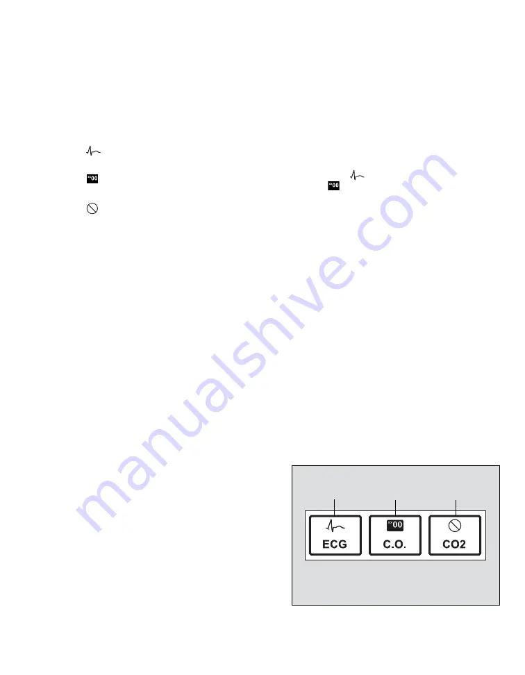
Each connected parameter is represented as a
small field on the auto view setup toolbar. The
following figure is an example of how the auto view
setup toolbar identifies the display mode of
parameters on the main screen. The symbols
above the parameter label identify the three
different display modes. The same symbols appear
in the parameter selection window of the
Auto view
page.
051
A
B
C


