


E X T E R N A L D M A
DMA buffer descriptor
340
Hardware Reference NS9215
. . . . . . . . . . . . . . . . . . . . . . . . . . . . . . . . . . . . . . . . . . . . . . . . . . . . . . . . . . . . . . . . . . . . . . . . . . . . . . . . . .
D M A b u f f e r d e s c r i p t o r
All DMA channels use a buffer descriptor. When a DMA channel is activated, it reads
the DMA buffer descriptor that the Buffer Descriptor Pointer register points to. A
DMA buffer descriptor is always fetched using an AHB INCR4 transaction to maximize
AHB bus bandwidth. When the current descriptor is retired, the next descriptor is
accessed from a circular buffer.
Each DMA buffer requires four 32-bit words to describe a transfer. Multiple buffer
descriptors are located in circular buffers of 4096 bytes. The DMA channel’s buffer
descriptor pointer provides the first buffer descriptor address. Subsequent buffer
descriptors are found adjacent to the first descriptor. The final buffer descriptor is
defined with its W bit set. When the DMA channel finds the W bit, the channel
wraps around to the first descriptor.
Each DMA channel can address a maximum of 256 buffer descriptors.
Important:
A DMA channel configured for more than the maximum number of
buffer descriptors operates in an unpredictable fashion.
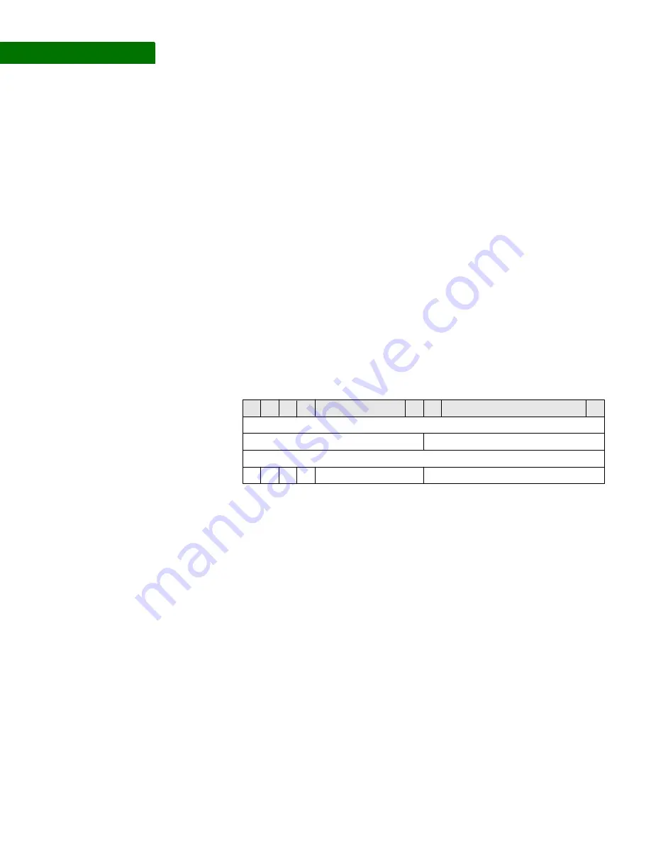
DMA buffer
descriptor
diagram
Field descriptions follow.
Source address
[pointer]
The source address pointer field identifies the starting location of the source data.
The source address can be aligned to any byte boundary.
Note:
Optimal performance is achieved when the source address is aligned on a
word boundary.
Buffer length
Buffer length indicates the number of bytes to move between the source and the
destination. After completing the transfer, the DMA controller updates this field with
the actual number of bytes moved. This is useful for debugging error conditions or
determining the number of bytes transferred before the DONE signal was asserted.
Destination
address [pointer]
The description address pointer field identifies the starting location of the source
data’s destination; that is, to where the source data needs to be moved. The
destination address can be aligned to any byte boundary.
Destination address
Buffer length
Status
Source address
8
F
I
L
W
Reserved
Reserved
31 30 29
28
16
15
0
0
C
4
Summary of Contents for NS9215
Page 1: ...NS9215 Hardware Reference 90000847_C Release date 10 April 2008...
Page 3: ......
Page 4: ......
Page 26: ...26 Hardware Reference NS9215...
Page 44: ...P I N O U T 26 5 System clock 44 Hardware Reference NS9215 System clock drawing...
Page 52: ...P I N O U T 26 5 Power and ground 52 Hardware Reference NS9215...
Page 80: ...I O C O N T ROL M O D U L E Memory Bus Configuration register 80 Hardware Reference NS9215...
Page 136: ...WOR KI N G W I TH T H E C P U Noncachable instruction fetches 136 Hardware Reference NS9215...
Page 202: ...S Y S T E M C O N T RO L M OD U L E RTC Module Control register 202 Hardware Reference NS9215...
Page 354: ...E X T E R N A L D M A DMA Peripheral Chip Select register 354 Hardware Reference NS9215...
Page 472: ...R E A L TI M E C L O C K M O D U L E General Status register 472 Hardware Reference NS9215...
Page 512: ...TI M I NG Clock timing 512 Hardware Reference NS9215...
Page 515: ...PA CKA GING Processor Dimensions www digiembedded com 515...
Page 516: ...PA CKA GING Processor Dimensions 516 Hardware Reference NS9215...