


E T H E R N E T C O M M U N I C A T I O N M O D U L E
Receive packet processor
268
Hardware Reference NS9215
Transferring a
frame to system
memory
The
RX_RD
logic manages the transfer of a frame in the RX_FIFO to system memory.
The transfer is enabled by setting the
ERXDMA
(enable receive DMA) bit in Ethernet
General Control Register #1.
Transferring a frame in the receive FIFO to system memory begins when the
RX_WR
logic notifies the
RX_RD
logic that a good frame is in the receive FIFO. Frames are
transferred to system memory using up to four rings (that is, 1, 2, or 3 rings can also
be used) of buffer descriptors that point to buffers in system memory. The
maximum frame size that each ring can accept is programmable. The first thing the
RX_RD
logic does, then, is analyze the frame length in the receive status FIFO to
determine which buffer descriptor to use.
The
RX_RD
logic goes through the four buffer descriptors looking for the optimum
buffer size. It searches the enabled descriptors starting with A, then B, C, and
finally D; any pools that are full (that is, the F bit is set in the buffer descriptor) are
skipped. The search stops as soon as the logic encounters an available buffer that is
large enough to hold the entire receive frame.
The pointers to the first buffer descriptor in each of the four pools are found in the
related Buffer Descriptor Pointer register (RXAPTR, RXBPTR, RXCPTR, RXDPTR).
Pointers to subsequent buffer descriptors are generated by adding an offset of
0x10
from this pointer for each additional buffer used.
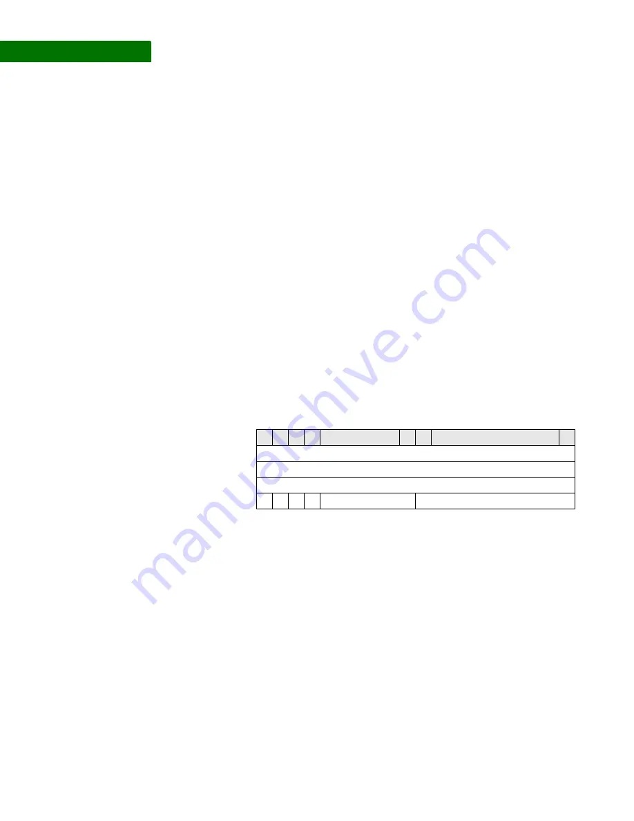
Receive buffer
descriptor format
Receive buffer
descriptor format
description
The current buffer descriptor for each pool is kept in local registers. The current
buffer descriptor registers are initialized to the buffer descriptors pointed to by the
Buffer Descriptor Pointer registers, by setting the
ERXINIT
(enable initialization of
RX
buffer descriptor registers) bit in Ethernet General Control Register #1. The
initialization process is complete when
RXINIT
(
RX
initialization complete) is set in
the Ethernet General Status register. At the end of a frame, the next buffer
descriptor for the ring just used is read from system memory and stored in the
registers internal to the
RX_RD
logic.
Destination Address (not used)
Buffer Length (11 lower bits used)
Status
Source Address
0
0
4
8
C
F
I
E
W
Reserved
31
15
16
30 29 28
Summary of Contents for NS9215
Page 1: ...NS9215 Hardware Reference 90000847_C Release date 10 April 2008...
Page 3: ......
Page 4: ......
Page 26: ...26 Hardware Reference NS9215...
Page 44: ...P I N O U T 26 5 System clock 44 Hardware Reference NS9215 System clock drawing...
Page 52: ...P I N O U T 26 5 Power and ground 52 Hardware Reference NS9215...
Page 80: ...I O C O N T ROL M O D U L E Memory Bus Configuration register 80 Hardware Reference NS9215...
Page 136: ...WOR KI N G W I TH T H E C P U Noncachable instruction fetches 136 Hardware Reference NS9215...
Page 202: ...S Y S T E M C O N T RO L M OD U L E RTC Module Control register 202 Hardware Reference NS9215...
Page 354: ...E X T E R N A L D M A DMA Peripheral Chip Select register 354 Hardware Reference NS9215...
Page 472: ...R E A L TI M E C L O C K M O D U L E General Status register 472 Hardware Reference NS9215...
Page 512: ...TI M I NG Clock timing 512 Hardware Reference NS9215...
Page 515: ...PA CKA GING Processor Dimensions www digiembedded com 515...
Page 516: ...PA CKA GING Processor Dimensions 516 Hardware Reference NS9215...