


Section 9
Testing
9.1
Set-up procedure
Equipment List
•
0 – 200 mA current supply with phase angle settings of 0° to +90°
•
90 – 145 Vac voltage source at 60 Hz
•
High impedance true RMS voltmeter with accuracy on ac of at least ±0.2% of reading
•
Accurate stop watch
The current input to the TCC300 is rated at 0.2 A continuous, 0.4 A for two
hours, and 4.0 A for 1 second.
Procedure
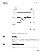
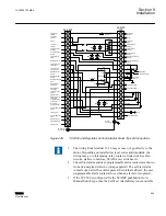
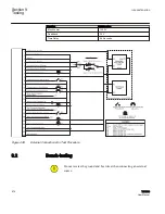
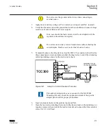
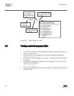
1. Make electrical connections as shown in
.
See Appendix A for the locations of screens within the software.
There is a one-second delay between the out-of-band condition and
panel LED indication.
2. Enter initial settings.
Table 70:
Initial settings
Function
Initial setting
Bandcenter
120.0 V
Bandwidth
2.0 V
LDC Resistance
0.0 V
LDC Reactance
0.0 V
Paralleling
Circulating Current Method
Block Raise
135.0 V
Table continues on next page
1VAC388793-MB A
Section 9
Testing
TCC300
575
User Manual
Summary of Contents for TCC300
Page 1: ...Digital Tapchanger Control TCC300 User Manual ...
Page 2: ......
Page 3: ...Document ID 1VAC388793 MB Issued 2016 08 10 Revision A Copyright 2016 ABB All rights reserved ...
Page 26: ...20 ...
Page 34: ...28 ...
Page 91: ...1VAC388793 MB A Section 3 Operation TCC300 85 User Manual ...
Page 126: ...120 ...
Page 176: ...Section 4 1VAC388793 MB A TCC600 170 TCC300 User Manual ...
Page 260: ...254 ...
Page 328: ...322 ...
Page 494: ...488 ...
Page 556: ...550 ...
Page 580: ...574 ...
Page 600: ...594 ...
Page 700: ...694 ...
Page 710: ...704 ...
Page 712: ...706 ...
Page 713: ...707 ...
Page 714: ......
Page 715: ......