


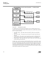


Thus, the information needed from an individual transformer is: the number of degrees per
tap (always 9 or 10), rotation of the Tap Position Sensor, and the number of neutral tap
positions. The sensor requires a +12 Vdc power input that is supplied from the TCC300
control via the M
‑
2025D. The electrical output of the M
‑
2948 Tap Position Sensor is a
4-20 mA current loop that is converted to a voltage signal at the input of the M-2025D
Current Loop Interface with the addition of a shunt resistor. The resultant voltage signal
is conditioned in the M-2025D Current Loop Interface and routed to the TCC300
Tapchanger Control where the voltage is converted to a corresponding tap position
number. The scheme can be used with all TCC300 Tapchanger Controls.
If replacing an INCON Tap Position Monitoring device, the INCON 1292 Synchro
Transmitter is removed and the ABB M-2948 Tap Position Sensor mounts in the existing
bracket and uses the existing flexible coupling shaft.
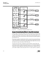
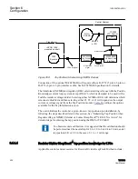
ABB-INCON Shaft Coupled KeepTrack Method
If tap position sensors already exist such as the INCON 1292 Synchro Transmitter, the
shaft coupled KeepTrack method is still applicable. The INCON 1292 Synchro
Transmitter is an electromagnetic device that resembles a small electric motor. Although
various configurations of internal windings are used, they typically excite rotor
winding(s), and induce AC signal voltages in the stator windings which can be compared
in amplitude and polarity to determine the angular position of the rotor shaft.
This application is traditionally used with the INCON 1250 Tap Position Monitoring
device. The INCON 1250 supplies the 120 Vac to the INCON 1292 rotor winding(s). It
then measures the resulting signals from the stator winding to determine the shaft's
rotational position. This information is converted to a tap number and displayed on the
front panel numeric readout. An analog current signal is also generated which corresponds
to tap position. The M-2025B(D) Current Loop Interface module accepts this current
analog. The scheme can be used with all TCC300 Load Tap Changer models.
1VAC388793-MB A
Section 6
Configuration
TCC300
453
User Manual
Summary of Contents for TCC300
Page 1: ...Digital Tapchanger Control TCC300 User Manual ...
Page 2: ......
Page 3: ...Document ID 1VAC388793 MB Issued 2016 08 10 Revision A Copyright 2016 ABB All rights reserved ...
Page 26: ...20 ...
Page 34: ...28 ...
Page 91: ...1VAC388793 MB A Section 3 Operation TCC300 85 User Manual ...
Page 126: ...120 ...
Page 176: ...Section 4 1VAC388793 MB A TCC600 170 TCC300 User Manual ...
Page 260: ...254 ...
Page 328: ...322 ...
Page 494: ...488 ...
Page 556: ...550 ...
Page 580: ...574 ...
Page 600: ...594 ...
Page 700: ...694 ...
Page 710: ...704 ...
Page 712: ...706 ...
Page 713: ...707 ...
Page 714: ......
Page 715: ......