


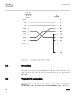


The control can be connected to fiber optics in two ways. If Fiber Repeat Switch on the
right side of control (as viewed from the rear) is set to OFF, the fiber interface is set in a
point
‑
to
‑
point configuration.
Example: A PC to one control. If Fiber Repeat Switch is set to ON, the control can be
connected in a loop or daisy chain (the TX of one control connected to the RX of the next,
etc.). When connecting the control in this manner through TCC600®, Echo Cancel should
be set to ON. The type of fiber used with these optical transceivers is multi mode fiber. It
was tested with fiber size 62.5/125. A manufacturer of this product is Amphenol
Corporation. A typical part number tested by ABB is 943
‑
32255
‑
10030 from Amphenol
Corporation, Lisle, Illinois. This is a dual-fiber with a total of four ST connectors.
943
-
X
X
X X
X X X X
-
X
X
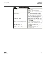
Cable Type
3 = 3 mm Jacketed
5 = 900
µ
m Jackete d
9 = 900
µ
m Tight Buffered
Assembly Type
0 = Pigtail
1 = Patch Cord (jumper)
2 = Duplex Patch Cord (jumper)
3 = Duplex Connector Pigtail (SC only)
4 = Duplex Connector Jumper (SC only)
Fiber Size
1 = 50/125
2 = 62.5/125
4 = 100/140
Amphenol Fiber Optic cable
P.N. Ordering
Connector Types
2 = FC
5 = ST
6 = SC
Side A
S ide B
Boot Type
1 = Standard
2 = Right Angle, Side A
3 = Right Angle, Side B
4 = Right Angle, Side A & B
Cable Length in Meters
(e.g., 0001 = 1m)
NOTE
(for connector types): If
assembly type = 0 (pigtail),
connector “type” digits are
identical (i.e., 66=SC pigtail).
If assembly type = 1 (jumper),
use combinations of the above
types for each end of the jumper.
Always use the lower number in
the first (A) position (i.e., 11 =
biconic to biconic; 26 = FC to
Super ST).
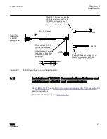
GUID-149D664C-5C56-4C49-85E4-9D52D17AEB5C V1 EN
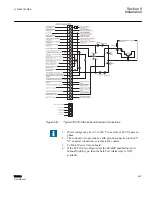
Figure 441:
Communication Connections
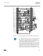
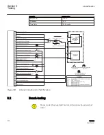
Ethernet (RJ-45 Interface)
The control includes an optional Ethernet Port (COM3) which is compatible with all
protocols in the control. There are eleven configuration screens in the HMI for setting up
the ethernet port: DHCP Enable, IP Address, Net Mask, Gateway, MODBUS® Port, DNP
Port, Auto Negotiation, Keepalive time, SNTP Enable, SNTP Server Address and Time
Zone.
The IP Address screen is used to set the address used to communicate with the control
(when DHCP is disabled). The IP Net Mask screen is used for multicasting.
The DHCP Mode screen, when enabled, will allow the control to use any available IP
address (which will be shown while booting the Ethernet during control power up. When
1VAC388793-MB A
Section 8
Installation
TCC300
563
User Manual
Summary of Contents for TCC300
Page 1: ...Digital Tapchanger Control TCC300 User Manual ...
Page 2: ......
Page 3: ...Document ID 1VAC388793 MB Issued 2016 08 10 Revision A Copyright 2016 ABB All rights reserved ...
Page 26: ...20 ...
Page 34: ...28 ...
Page 91: ...1VAC388793 MB A Section 3 Operation TCC300 85 User Manual ...
Page 126: ...120 ...
Page 176: ...Section 4 1VAC388793 MB A TCC600 170 TCC300 User Manual ...
Page 260: ...254 ...
Page 328: ...322 ...
Page 494: ...488 ...
Page 556: ...550 ...
Page 580: ...574 ...
Page 600: ...594 ...
Page 700: ...694 ...
Page 710: ...704 ...
Page 712: ...706 ...
Page 713: ...707 ...
Page 714: ......
Page 715: ......